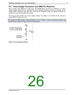
TMC248-LA DATASHEET (Rev. 1.01 / 2013-MAR-26)
30
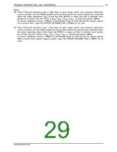
12 Layout Considerations
For optimal operation of the circuit a careful board layout is important, because of the combination of
high current chopper operation coupled with high accuracy threshold comparators.
12.1 Grounding
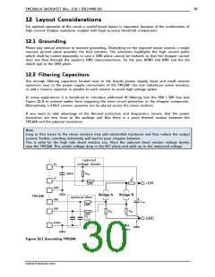
Please pay special attention to massive grounding. Depending on the required motor current, a single
massive ground plane provides the best solution. The schematic highlights the high current paths
which shall be routed separately, in case a GND plane cannot be realized, so that the chopper current
does not flow through the system’s GND interconnections. Tie the pins AGND and GND and the die
attach pad to the GND plane.
12.2 Filtering Capacitors
Use enough filtering capacitors located near to the boards power supply input and small ceramic
capacitors near to the power supply connections of the TMC248. Use low inductance sense resistors,
or add a ceramic capacitor in parallel to each resistor to avoid high voltage spikes.
In many applications it is beneficial to introduce additional RC-filtering into the SRA / SRB line (see
Figure 12.1) to prevent spikes from triggering the short circuit protection or the chopper comparator.
Alternatively, a 470nF ceramic capacitor can be placed across the sense resistors.
If you want to take advantage of the thermal protection and diagnostics, ensure, that the power
transistors are very close to the package and that there is a good thermal contact between the
TMC248 and the external transistors.
Note:
Long or thin traces to the sense resistors may add substantial resistance and thus reduce the output
current. Further, resulting inductivity will lead to poor chopper behavior.
This is valid for the high side shunt resistor, too. Place the optional shunt resistor voltage divider
near the TMC248. This avoids voltage drop in the VCC plane and adds up to the measured voltage.
optional
voltage divider
VS
100nF
RDIV
VT
+VM
100R
GND
Bridge A
Bridge B
TMC248
optional filter
SRA
SRB
CVM
100R
RSA
RSB
100R
2.2 -
GND
4.7nF
AGND
GND-
Plane
Figure 12.1 Grounding TMC248
www.trinamic.com

 TRINAMIC [ TRINAMIC MOTION CONTROL GMBH & CO. KG. ]