TLP250H,TLP250HF
9. Recommended Operating Conditions (Note)
Characteristics
Symbol
Note
Min
Typ.
Max
Unit
Input on-state current
Input off-state voltage
Supply voltage
IF(ON)
VF(OFF)
VCC
(Note 1)
6.5
0
10
0.8
mA
V
(Note 2)
10
30
Peak high-level output current
Peak low-level output current
Operating frequency
IOPH
IOPL
f
-2.0
+2.0
250
A
(Note 3)
kHz
Note: The recommended operating conditions are given as a design guide necessary to obtain the intended
performance of the device. Each parameter is an independent value. When creating a system design using
this device, the electrical characteristics specified in this datasheet should also be considered.
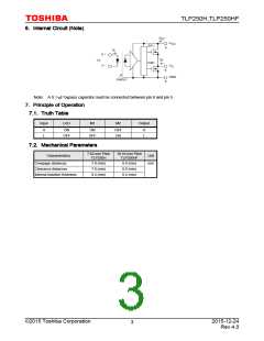
Note: A ceramic capacitor (0.1 µF) should be connected between pin 8 and pin 5 to stabilize the operation of a high-
gain linear amplifier. Otherwise, this photocoupler may not switch properly. The bypass capacitor should be
placed within 1 cm of each pin.
Note : If the rising slope of the supply voltage (VCC) for the detector is steep, stable operation of the internal circuits
cannot be guaranteed.
Be sure to set 3.0 V/µs or less for a rising slope of the VCC.
Note 1: The rise and fall times of the input on-current should be less than 0.5 µs.
Note 2: Denotes the operating range, not the recommended operating condition.
Note 3: Exponential waveform. IOPH ≥ -0.65 A (≤ 80 ns), IOPL ≤ 0.65 A (≤ 80 ns), Ta = 125 , VCC = 20 V
©2015 Toshiba Corporation
2015-12-24
Rev.4.0
5
图片预览")
 TOSHIBA [ TOSHIBA ]