UCD9090
SLVSA30A –APRIL 2011–REVISED AUGUST 2011
www.ti.com
FAULT RESPONSES AND ALERT PROCESSING
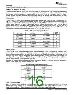
Device monitors that the rail stays within a window of normal operation. There are two programmable warning
levels (under and over) and two programmable fault levels (under and over). When any monitored voltage goes
outside of the warning or fault window, the PMBALERT# pin is asserted immediately, and the appropriate bits are
set in the PMBus status registers (see Figure 7). Detailed descriptions of the status registers are provided in the
UCD90xxx Sequencer and System Health Controller PMBus Command Reference and the PMBus Specification.
A programmable glitch filter can be enabled or disabled for each MON input. A glitch filter for an input defined as
a voltage can be set between 0 and 102 ms with 400-μs resolution.
Fault-response decisions are based on results from the 12-bit ADC. The device cycles through the ADC results
and compares them against the programmed limits. The time to respond to an individual event is determined by
when the event occurs within the ADC conversion cycle and the selected fault response.
PMBUS_CNTRL PIN
TIME BETWEEN
RESTARTS
TIME BETWEEN
RESTARTS
TIME BETWEEN
RESTARTS
TON_DELAY[1]
TOFF_DELAY[1]
MAX_GLITCH_TIME
RAIL 1 EN
VOUT_OV_FAULT_LIMIT
MAX_GLITCH_TIME +
TOFF_DELAY[1]
MAX_GLITCH_TIME +
TOFF_DELAY[1]
VOUT_UV_FAULT_LIMIT
POWER_GOOD_ON[1]
MAX_GLITCH_TIME
MAX_GLITCH_TIME
TOFF_DELAY[1]
RAIL 1 VOLTAGE
TON_DELAY[2]
TOFF_DELAY[2]
RAIL 2 EN
RAIL 2 VOLTAGE
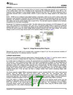
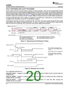
Rail 1 and Rail 2 are both sequenced “ON” and
“OFF” by the PMBUS_CNTRL pin only
Rail 1 is set to use the glitch filter for UV or OV events
Rail 1 is set to RESTART 3 times after a UV or OV event
Rail 1 is set to shutdown with delay for a OV event
Rail 2 has Rail 1 as an “ON” dependency
Rail 1 has Rail 2 as a Fault Shutdown Slave
Figure 14. Sequencing and Fault-Response Timing
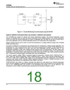
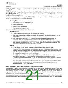
PMBUS_CNTRL PIN
TON_DELAY[1]
Rail 1 and Rail 2 are both sequenced
“ON” and “OFF” by the PMBUS_CNTRL
pin only
RAIL 1 EN
Time Between Restarts
Rail 2 has Rail 1 as an “ON” dependency
Rail 1 is set to shutdown immediately
and RESTART 1 time in case of a Time
On Max fault
POWER_GOOD_ON[1]
POWER_GOOD_ON[1]
RAIL 1 VOLTAGE
TON_MAX_FAULT_LIMIT[1]
TON_DELAY[2]
TON_MAX_FAULT_LIMIT[1]
RAIL 2 EN
RAIL 2 VOLTAGE
Figure 15. Maximum Turn-on Fault
The configurable fault limits are:
TON_MAX_FAULT – Flagged if a rail that is enabled does not reach the POWER_GOOD_ON limit within the
configured time
VOUT_UV_WARN – Flagged if a voltage rail drops below the specified UV warning limit after reaching the
POWER_GOOD_ON setting
VOUT_UV_FAULT – Flagged if a rail drops below the specified UV fault limit after reaching the
POWER_GOOD_ON setting
20
Copyright © 2011, Texas Instruments Incorporated

 TI [ TEXAS INSTRUMENTS ]