UCD8220, UCD8620
www.ti.com
SLUS652B–MARCH 2005–REVISED SEPTEMBER 2005
APPLICATION INFORMATION
operating frequency and maximum duty cycle limit
and hence controls the power supply operation as
listed above. The pulse train uses a Texas Instru-
ments communication protocol which is a proprietary
communication system that provides handles for
control of the power supply operation through
software programming. The rising edge of the CLK
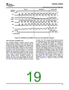
signal represents the switching frequency. Figure 39
depicts the operation of the UCD8K device in one of
5 modes. At the time when the internal signal REF
OK is low, the UCD8K device is not ready to accept
CLK inputs. Once the REF OK signal goes high, then
the device is ready to process inputs. While the CLK
input is low, the outputs are disabled and the CLK
signal is used as an enable input. Once the Digital
controller completes its initialization routine and ver-
ifies that all voltages are within their operating range,
then it starts the soft-start procedure by slowly
ramping up the duty cycle of the CLK signal, while
maintaining the desired switching frequency. The duty
cycle continues to increase until it reaches
steady-state where the analog control loop takes over
and regulates the output voltage to the desire set
point. During steady state, the maximum duty cycle
can be set using a volt second product calculation in
order to protect the primary of the power transformer
from saturation during transients. When the power
supply enters current limit, the outputs are quickly
turned off, and the CLF signal is set high in order to
notify the digital controller that the last power pulse
was truncated because of an overcurrent event. The
benefit of this technique is in the flexibility it offers.
The software is now in charge of the response to
overcurrent events. In typical analog designs, the
power supply response to overcurrent is hardwired in
the silicon. With this method, the user can configure
the response differently for different applications. For
example, the software can be configured to latch-off
the power supply in response the first overcurrent
event, or to allow a fixed number of current limit
events, so that the supply is capable of starting up
into a capacitive load. The user can also configure
the supply to enter into hiccup mode immediately or
after a certain number of current limit events. As
described later in this data sheet, the current limit
threshold can be varied in time to create unique
current limit profiles. For example, the current limit set
point can be set high for a predefined number of
cycles to blow a manual fuse, and can be reduced
down to protect the system in the event of a faulty
fuse.
Introduction
The UCD8220 and UCD8620 are digitally managed
analog PWM controllers configured with push-pull
drive logic. The UCD8620 has a 110-V high-voltage
startup circuit which can directly start up the controller
from a 48-V telecom input line.
In systems using UCD8K devices, the PWM feedback
loop is closed using the traditional analog methods,
but the UCD8K controllers include circuitry to interpret
a time-domain digital pulse train from a digital control-
ler. The pulse train contains the operating frequency
and maximum duty cycle limit and hence controls the
power supply operation. This eases implementing a
converter with high-level control features without the
added complexity or digital PWM resolution limi-
tations encountered when closing the voltage control
loop in the discrete time domain.
The UCD8220 and UCD8620 can be configured for
either peak current mode or voltage mode control.
They provide a programmable current limit function
and a digital output current limit flag which can be
monitored by the host controller. For fast switching
speeds, the output stages use the TrueDrive™ output
architecture, which delivers rated current of ±4 A into
the gate of a MOSFET during the Miller plateau
region of the switching transition. Finally they also
include a 3.3-V, 10-mA linear regulator to provide
power for the digital controller.
The UCD8620 includes circuitry and features to ease
implementing a converter that is managed by a
microcontroller or a digital signal processor. Digitally
managed
power
supplies
provide
software
programmability and monitoring capability of the
power supply operation including:
•
•
•
•
•
•
•
•
•
•
Switching frequency
Synchronization
DMAX
V x S clamp
Input UVLO start/stop voltage
Input OVP start/stop voltage
Soft-start profile
Current limit operation
Shutdown
Temperature shutdown
CLK Input Time-Domain Digital Pulse Train
While the loop is closed in the analog domain, the
UCD8K devices are managed by a time-domain
digital pulse train from a digital controller. The pulse
train, shown as CLK in Figure 39, contains the
18

 TI [ TEXAS INSTRUMENTS ]