UCC28610
www.ti.com ......................................................................................................................................... SLUS888C–JANUARY 2009–REVISED SEPTEMBER 2009
Typical Schematic and Layout
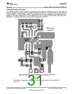
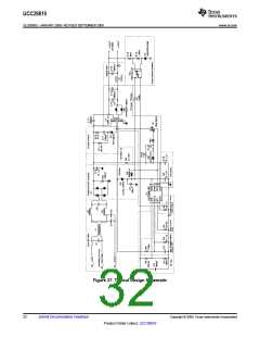
It is possible to design a power supply on a single layer board using the UCC28610. Figure 36 and Figure 37
show an example of a typical layout and design, respectively. Proper use of ground planes can solve EMI and
thermal problems. For best results, create a quiet ground plane for the components associated with pins 1
through 4. This offers shielding for the control signals. Also, do not extend the ground plane under heat sinks,
thermistors or snubbers so that these components do not heat the UCC28610.
Figure 36. Typical Layout of the Device on a Single Layer PCB
NOTE:
The reference designators correspond to the components shown in the schematic of
Figure 37.
Copyright © 2009, Texas Instruments Incorporated
Submit Documentation Feedback
31
Product Folder Link(s): UCC28610

 TI [ TEXAS INSTRUMENTS ]