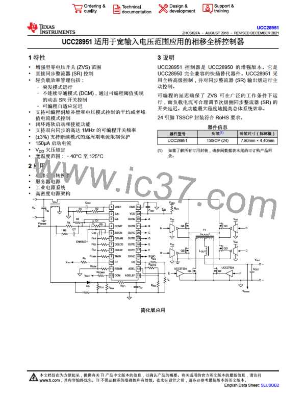
UCC28951
www.ti.com.cn
ZHCSIQ7A –AUGUST 2018 –REVISED DECEMBER 2021
Calculate average Coss [2] using 方程式49:
VdsQA
COSS _ QA _ AVG = COSS _ QA _ SPEC
» 193pF
V
INMAX
(49)
(50)
(51)
(52)
(53)
The QA FET gate charge is:
QAg = 15nC
The voltage applied to FET gate to activate FET is:
Vg = 12V
Calculate QA losses (PQA) based on Rds(on)QA and gate charge (QAg) using 方程式52:
P = IPRMS2 ìRDS(on)QA + 2ìQAg ì Vg ì fSW ö 2.1W
QA
Recalculate the power budget using 方程式53:
P
= P
- 4´PQA » 29.7W
BUDGET
BUDGET
8.2.2.4 Selecting LS
Calculating the value of the shim inductor (LS) is based on the amount of energy required to achieve zero
voltage switching. This inductor needs to able to deplete the energy from the parasitic capacitance at the switch
node. 方程式 54 selects LS to achieve ZVS at 100% load down to 50% load based on the primary FET’s
average total COSS at the switch node.
备注
The actual parasitic capacitance at the switched node may differ from the estimate and LS may have
to be adjusted accordingly.
2
V
INMAX
L ³ 2´C
-LLK » 26mH
(
)
I
æ
PP
S
OSS _ QA _ AVG
ö2
DILOUT
2´a1
-
ç
÷
ø
2
è
(54)
For this design, a 26-µH Vitec inductor was chosen for LS, part number 60PR964. The shim inductor has the
following specifications:
LS = 26mH
(55)
The LS DC Resistance is:
DCRLS = 27mW
(56)
Estimate LS power loss (PLS) and readjust remaining power budget using 方程式57 through 方程式58:
Copyright © 2023 Texas Instruments Incorporated
English Data Sheet: SLUSDB2
50
Submit Document Feedback
Product Folder Links: UCC28951

 TI [ TEXAS INSTRUMENTS ]