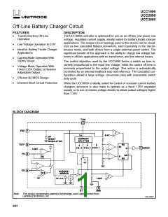
UCC1890
UCC2890
UCC3890
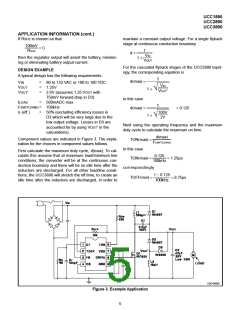
APPLICATION INFORMATION (cont.)
low the regulation point of 1.25V. The minimum value ple clamp on the output may not be adequate. In current
sense mode it is recommended that a second zener be
connected from the output to the FB pin, the breakdown
voltage of this clamp chosen to be high enough so that
it will not conduct during normal operation, but will con-
duct at least 2V lower than the breakdown voltage of
the other clamp.
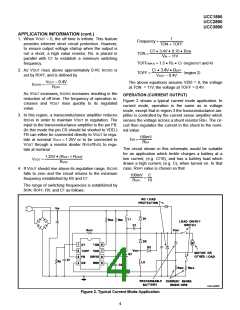
for TOFF is 8.75µs. So in this case
8.75µs • (1.24V − 0.4V)
ROFF =
= 15k
150pF • 3.4V
OTHER APPLICATION CONSIDERATIONS
Output Capacitor: For best regulation of the output
voltage or current, the output capacitor should be a low
ESR type. This is especially true when operating in cur-
rent sense mode with a non-linear load such as a bat-
tery. If a low ESR capacitor cannot be used, excellent
regulation can also be achieved by placing a low pass
R/C filter between the current shunt and the CS input.
Gate Drive for the External FET: The UCC3890 is
guaranteed to be able to deliver at least 1mA of steady
state current to the gate of the external FET at ITON =
2mA. If ITON is higher than 2mA, 80% of the additional
current is available to drive the FET gate. If, as in the
design example above, a moderate sized FET such as
the IRF820 is used, the operating frequency is 100kHz,
and the minimum ITON at low line is 2.8mA, then the
available gate drive current may be adequate. The
IRF820 needs about 13nC to charge the gate on each
cycle. At 100kHz, this is equivalent to 1.3mA steady
state; below the minimum 1.64mA available. In some
combinations of a larger FET, and/or higher frequency
operation, the current available for driving the gate may
not be adequate. In that case extra current may be pro-
vided by connecting a resistor RDD from the line input to
the VDD pin. This resistor should be sized so that under
all conditions the current input to VDD is below the
7.5mA absolute maximum limit. RDD will likely need to
be a power resistor.
No Load Operation: The UCC3890 is inherently pro-
tected for short circuits, but not for open circuits. If the
load is removed, the output voltage will quickly rise up
to the regulation point. Once the output is above the
regulation voltage, the oscillator will drop to the mini-
mum frequency set by RS/CT. With no load on the out-
put, even at this low frequency the output voltage can
quickly rise to a dangerous level. To protect against this,
it is recommended that a zener or other voltage clamp
always be connected across the output. The clamp
should be chosen to be above the normal range of out-
put voltage, but low enough to protect the output ca-
pacitor. In current sense operation, removal of the load
will also break the regulation loop, in which case a sim-
UNITRODE CORPORATION
7 CONTINENTAL BLVD. • MERRIMACK, NH 03054
TEL. (603) 424-2410 • FAX (603) 424-3460
7

 TI [ TEXAS INSTRUMENTS ]