UCC1890
UCC2890
UCC3890
PIN DESCRIPTIONS
CS: The high side of the current sense shunt is con- TOFF: Resistor ROFF connects from voltage output to
nected to this pin. Short CS to VDD for voltage feedback this pin to provide a maximum capacitor discharge cur-
operation.
rent proportional to output voltage.
CT: Oscillator timing capacitor is connected to this pin.
DRIVE: Gate drive to external power switch.
TON: Resistor RON connects from line input to this pin to
provide capacitor charge current proportional to line volt-
age. The current in RON also provides power for the 9V
shunt regulator at VDD.
FB: Output of current sense amplifier. This pin can be
used for direct output voltage feedback if the current
sense amp input pin CS is shorted to the VDD pin.
VDD: Output of 9V shunt regulator.
GND: Ground pin.
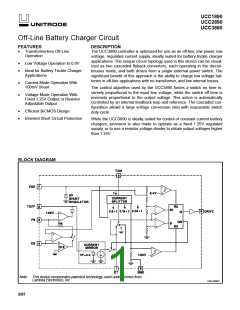
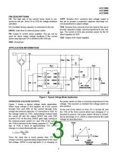
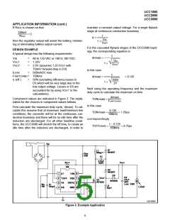
APPLICATION INFORMATION
UDG-96053
Figure 1. Typical Voltage Mode Application
OPERATION (VOLTAGE OUTPUT)
the power switch on time is inversely proportional to line
voltage. This provides a constant line voltage-switch on
time product.
Figure 1 shows a typical voltage mode application.
When input voltage is first applied, all of the current
through RDD and 80% of the current through RON,
charge the external capacitor C3 connected to VDD. As
the voltage builds on VDD, undervoltage lockout holds
the circuit off and the output DRIVE low until VDD
reaches 8.4V. At this time, DRIVE goes high, turning on
the external power switch Q1, and 15% of the current
into TON is directed to the timing capacitor CT. The volt-
age at TON is fixed at approximately 11V, so CT
charges to a fixed threshold with current
At the end of the switch on time, Q1 is turned off, and
the 15% of the RON current which was charging CT is
diverted to ground. The power switch off time is control-
led by discharge of CT, which is determined by the outut
voltage as described here:
VIN – 11V
I = 0.2 •
RON
Since the input line is much greater than 11V, the
charge current is approximately proportional to the input
line voltage. DRIVE is only high while CT is charging, so
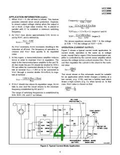
UDG-96054
3

 TI [ TEXAS INSTRUMENTS ]