UCC1890
UCC2890
UCC3890
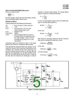
APPLICATION INFORMATION (cont.)
The average input current at minimum line and maxi- entire range of operation must be considered to choose
mum load will be
values for the rest of the components.
Under all normal operating conditions the current ITON,
(which is the current in RON), should be greater than
2mA and less than 7.5mA. In this case set RON to give
ITON = 2.8mA at low line. The voltage at TON will be
about 11V so
VOUT′
VIN
IOUT
η
IIN =
•
in this case
500mA
0.5
2V
100V
IIN =
•
= 20mA
100V − 11V
RON =
= 33kΩ
Knowing that input current is drawn from the line only
during TON, calculate the peak current in L1 to be
2.8mA
With RON = 33k, ITON at high line will be
TON + TOFF
IL1(pk) = 2 • IIN •
TON
180V − 11V
ITON =
= 5.1mA
33k
in this case
At high line, the power dissipation in RON will be
1.25µs + 8.75µs
P(RON) = (180V − 11V) • 5.1mA = 860mW
IL1(pk) = 2 • 20mA •
= 320mA
1.25µs
RON will need to be at least a 1W resistor. Alternately it
could be four 1/4W 8.2kΩ resistors in series.
Now calculate the value for L1
TON
L1 = VIN •
Once RON is set, CT can be chosen. The charge current
for CT is nominally 15% of ITON, and the nominal oscilla-
tor amplitude is 3.4V, so
IL1(pk)
in this case
CT • 3.4V
TON =
1.25µs
320mA
L1 = 100V •
= 390µH
0.15 • ITON
solving for CT
The output voltage of the first flyback stage is
TON • 0.15 • ITON
TON
VC1 = VIN •
TOFF
CT =
3.4V
ITON at low line is 2.8mA, and the target TON at low line
in this case
is 1.25µs, so in this case
1.25µs
VC1 = 100V •
= 14.3V
1.25µs • 0.15 • 2.8mA
8.75µs
CT =
= 150pF
3.4V
Knowing that output current is provided to the load only
during TOFF, calculate the peak current in L2 to be
The final component to be chosen is ROFF, which deter-
mines the minimum value of TOFF. When the output
voltage is below the regulation point, the discharge cur-
rent for CT is equal to ITOFF (the current in ROFF). Un-
der that condition
TON + TOFF
IL2(pk) = 2 • IOUT •
TOFF
in this case
CT • 3.4V
TOFF =
1.25µs + 8.75µs
IL2(pk) = 2 • 0.5A •
= 1.14A
ITOFF
8.75µs
since the voltage at the TOFF pin = 0.4V
Now calculate the value of L2
VOUT − 0.4V
ITOFF =
TOFF
L2 = VOUT′ •
IL2(pk)
ROFF
substituting and solving for ROFF
in this case
TOFF • (VOUT − 0.4V)
ROFF =
8.75µs
1.14A
L2 = 2V •
= 15µH
CT • 3.4V
The largest discharge current, and hence the minimum
off time, will occur when the output is about 10mV be-
For all of the calculations so far only the maximum
load/minimum line condition have been considered. The
6

 TI [ TEXAS INSTRUMENTS ]