UCC28180
SLUSBQ5A –NOVEMBER 2013–REVISED NOVEMBER 2013
www.ti.com
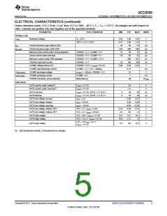
DEVICE INFORMATION
SOIC (TOP VIEW)
GND
GATE
VCC
1
2
3
4
8
7
6
5
ICOMP
ISENSE VSENSE
FREQ
VCOMP
PIN FUNCTIONS
NAME
GATE
I/O
PIN #
FUNCTION
Gate Drive: Integrated push-pull gate driver for one or more external power MOSFETs. Typical 2.0-A sink
and 1.5-A source capability. Output voltage is typically clamped at 15.2 V (typical).
O
8
1
GND
Ground: device ground reference.
Current Loop Compensation: Transconductance current amplifier output. A capacitor connected to GND
provides compensation and averaging of the current sense signal in the current control loop. The controller is
disabled if the voltage on ICOMP is less than 0.2 V, (ICOMPP protection function).
ICOMP
O
I
2
Inductor Current Sense: Input for the voltage across the external current sense resistor, which represents
the instantaneous current through the PFC boost inductor. This voltage is averaged by the current amplifier to
eliminate the effects of ripple and noise. Soft Over Current (SOC) limits the average inductor current. Cycle-
by-cycle peak current limit (PCL) immediately shuts off the GATE drive if the peak-limit voltage is exceeded.
An internal 2.3-µA current source pulls ISENSE above 0.085 V to shut down PFC operation if this pin
becomes open-circuited, (ISOP protection function). Use a 220-Ω resistor between this pin and the current
sense resistor to limit inrush-surge currents into this pin.
ISENSE
VCC
3
Device Supply: External bias supply input. Under-Voltage Lockout (UVLO) disables the controller until VCC
exceeds a turn-on threshold of 11.5 V. Operation continues until VCC falls below the turn-off (UVLO)
threshold of 9.5 V. A ceramic by-pass capacitor of 0.1 µF minimum value should be connected from VCC to
GND as close to the device as possible for high-frequency filtering of the VCC voltage.
7
Voltage Loop Compensation: Transconductance voltage error amplifier output. A resistor-capacitor network
connected from this pin to GND provides compensation. VCOMP is held at GND until VCC, and VSENSE
exceed their threshold voltages. Once these conditions are satisfied, VCOMP is charged until the VSENSE
voltage reaches its nominal regulation level. When Enhanced Dynamic Response (EDR) is engaged, a higher
transconductance is applied to VCOMP to reduce the charge or discharge time for faster transient response.
Soft Start is programmed by the capacitance on this pin. VCOMP is pulled low when VCC UVLO,
OLP/Standby, ICOMPP and ISOP functions are activated.
VCOMP
FREQ
O
O
5
4
Switching Frequency Setting: This pin allows the setting of the operating switching frequency by connecting
a resistor to ground. The programmable frequency range is from 18 kHz to 250 kHz.
Output Voltage Sense: An external resistor-divider network connected from this pin to the PFC output
voltage provides feedback sensing for regulation to the internal 5-V reference voltage. A small capacitor from
this pin to GND filters high-frequency noise. Standby disables the controller and discharges VCOMP when
the voltage at VSENSE drops below the Open-Loop Protection (OLP) threshold of 16.5%VREF (0.82 V). An
internal 100-nA current source pulls VSENSE to GND during pin disconnection. Enhanced Dynamic
Response (EDR) rapidly returns the output voltage to its normal regulation level when a system line or load
step causes VSENSE to rise above 105% or fall below 95% of the reference voltage. Two level Output Over-
Voltage Protection (OVP): a 4-kΩ resistor connects VCOMP to ground to rapidly discharge VCOMP when
VSENSE exceeds 107% (VOVP_L) of the reference voltage. If VSENSE exceeds 109% (VOVP_H) of the
reference voltage, GATE output will be disabled until VSENSE drops below 102% of the reference voltage.
VSENSE
I
6
6
Submit Documentation Feedback
Copyright © 2013, Texas Instruments Incorporated
Product Folder Links :UCC28180

 TI [ TEXAS INSTRUMENTS ]