UCC28180
www.ti.com
SLUSBQ5A –NOVEMBER 2013–REVISED NOVEMBER 2013
The voltage error amplifier is compensated with a zero, fZERO, at the fPWM_PS pole and a pole, fPOLE, placed at 20
Hz to reject high frequency noise and roll off the gain amplitude. The overall voltage loop crossover, fV, is desired
to be at 10 Hz. The compensation components of the voltage error amplifier are selected accordingly.
1
fZERO
=
2pRVCOMPCVCOMP
(109)
(110)
1
fPOLE
=
RVCOMPCVCOMPCVCOMP _ P
2p
C
VCOMP + CVCOMP _ P
é
ù
ú
ú
ú
ú
ú
ê
ê
ê
ê
ê
1+ s(f)RVCOMPCVCOMP
GEA(f) = gmv
é
ù
ú
ú
û
æ
ç
ç
è
ö
÷
÷
ø
RVCOMPCVCOMPCVCOMP _ P
C
(
VCOMP + CVCOMP _ P s(f)ê1+ s(f)
)
CVCOMP + CVCOMP _ P
ê
ë
ê
ë
ú
û
(111)
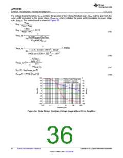
From Figure 34, the gain of the voltage transfer function at 10 Hz is approximately 0.081 dB. Estimating that the
parallel capacitor, CVCOMP_P, is much smaller than the series capacitor, CVCOMP, the unity gain will be at fV, and
the zero will be at fPWM_PS, the series compensation capacitor is determined:
fV = 10Hz
(112)
fV
gmv
fPWM_ PS
(f)
CVCOMP
=
0-G
VLdB
20
10
´ 2pfV
(113)
(114)
10Hz
56ms ´
1.479Hz
CVCOMP
=
= 6.08mF
0-0.081dB
20
10
The capacitor for VCOMP must have a voltage rating that is greater than the absolute maximum voltage rating of
the VCOMP pin, which is 7 V. The readily available standard value capacitor that is rated for at least 10 V in the
package size that would fit the application was 4.7 µF and this is the value used for CVCOMP in this design
example.
RVCOMP is calculated using the actual CVCOMP capacitor value.
CVCOMP = 4.7mF
(115)
1
RVCOMP
=
2pfZEROCVCOMP
(116)
(117)
1
RVCOMP
=
= 22.89kW
2´ p ´1.479Hz ´ 4.7mF
A 22.6-kΩ resistor is used for RVCOMP
.
CVCOMP
CVCOMP _ P
=
2pfPOLERVCOMPCVCOMP -1
(118)
(119)
4.7mF
CVCOMP _ P
=
= 0.381mF
2´ p ´ 20Hz ´ 22.6kkW ´ 4.7mF -1
A 0.47-µF capacitor is used for CVCOMP_P
.
Copyright © 2013, Texas Instruments Incorporated
Submit Documentation Feedback
37
Product Folder Links :UCC28180

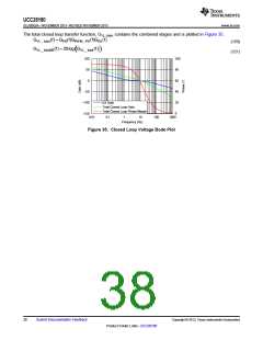
 TI [ TEXAS INSTRUMENTS ]