UCC28180
www.ti.com
SLUSBQ5A –NOVEMBER 2013–REVISED NOVEMBER 2013
Current Loop
The overall system current loop consists of the current averaging amplifier stage, the pulse width modulator
(PWM) stage, the external boost inductor stage and the external current sensing resistor.
ISENSE and ICOMP Functions
The negative polarity signal from the current sense resistor is buffered and inverted at the ISENSE input. The
internal positive signal is then averaged by the current amplifier (gmi), whose output is the ICOMP pin. The
voltage on ICOMP is proportional to the average inductor current. An external capacitor to GND is applied to the
ICOMP pin for current loop compensation and current ripple filtering. The gain of the averaging amplifier is
determined by the internal VCOMP voltage. This gain is non-linear to accommodate the world-wide AC-line
voltage range.
ICOMP is connected to 3-V internally whenever OVP_H, ISOP, or OLP is triggered.
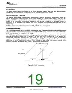
Pulse Width Modulator
The PWM stage compares the ICOMP signal with a periodic ramp to generate a leading-edge-modulated output
signal which is high whenever the ramp voltage exceeds the ICOMP voltage. The slope of the ramp is defined by
a non-linear function of the internal VCOMP voltage.
The PWM output signal always starts low at the beginning of the cycle, triggered by the internal clock. The output
stays low for a minimum off-time, tOFF_min, after which the ramp rises linearly to intersect the ICOMP voltage. The
ramp-ICOMP intersection determines tOFF, and hence DOFF. Since DOFF = VIN/VOUT by the boost-topology
equation, and since VIN is sinusoidal in wave-shape, and since ICOMP is proportional to the inductor current, it
follows that the control loop forces the inductor current to follow the input voltage wave-shape to maintain boost
regulation. Therefore, the average input current is also sinusoidal in wave-shape.
PWM cycle
VICOMP
VRAMP = F(VCOMP
)
tON
tOFF
Figure 29. PWM Generation
Copyright © 2013, Texas Instruments Incorporated
Submit Documentation Feedback
19
Product Folder Links :UCC28180

 TI [ TEXAS INSTRUMENTS ]