UCC27523, UCC27524, UCC27525, UCC27526
www.ti.com
SLUSAQ3F –NOVEMBER 2011–REVISED MAY 2013
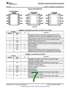
DEVICE INFORMATION
UCC27523,4,5(D,DGN) &
UCC27524P
(TOP VIEW)
UCC2752(3,4,5)DSD
(TOP VIEW)
UCC27526 DSD
(TOP VIEW)
1
2
8
7
1
2
8
7
ENA
INA
ENB
ENA
INA
ENB
1
2
8
7
INA-
INB-
INA+
INB+
OUTA
OUTA
3
4
6
5
3
4
6
5
GND
INB
VDD
3
4
6
5
GND
INB
VDD
GND
OUTA
VDD
OUTB
OUTB
OUTB
Figure 5.
TERMINAL FUNCTIONS (UCC27523 / UCC27524 / UCC27525)
TERMINAL
I/O
FUNCTION
NUMBER
NAME
1
ENA
I
Enable input for Channel A: ENA biased LOW Disables Channel A output
regardless of INA state, ENA biased HIGH or floating Enables Channel A output,
ENA allowed to float hence the pin-to-pin compatibility with UCC2732X N/C pin.
2
INA
I
Input to Channel A: Inverting Input in UCC27523, Non-Inverting Input in UCC27524,
Inverting Input in UCC27525, OUTA held LOW if INA is unbiased or floating.
3
4
GND
INB
-
I
Ground: All signals referenced to this pin.
Input to Channel B: Inverting Input in UCC27523, Non-Inverting Input in UCC27524,
Non-Inverting Input in UCC27525, OUTB held LOW if INB is unbiased or floating.
5
6
7
8
OUTB
VDD
O
I
Output of Channel B
Bias supply input
OUTA
ENB
O
I
Output of Channel A
Enable input for Channel B: ENB biased LOW Disables Channel B output
regardless of INB state, ENB biased HIGH or floating Enables Channel B output,
ENB allowed to float hence the pin-to-pin compatibility with UCC2732X N/C pin.
TERMINAL FUNCTIONS (UCC27526)
TERMINAL
I/O
FUNCTION
NUMBER
NAME
1
INA-
I
Inverting Input to Channel A: When Channel A is used in Non-Inverting
configuration, connect INA- to GND in order to Enable Channel A output, OUTA held
LOW if INA- is unbiased or floating.
2
INB-
I
Inverting Input to Channel B: When Channel B is used in Non-Inverting
configuration, connect INB- to GND in order to Enable Channel B output, OUTB held
LOW if INB- is unbiased or floating.
3
4
5
6
7
GND
OUTB
VDD
-
I
Ground: All signals referenced to this pin.
Output of Channel B
O
I
Bias Supply Input
OUTA
INB+
Output of Channel A
O
Non-Inverting Input to Channel B: When Channel B is used in Inverting
configuration, connect INB+ to VDD in order to Enable Channel B output, OUTB held
LOW if INB+ is unbiased or floating.
8
INA+
I
Non-Inverting Input to Channel A: When Channel A is used in Inverting
configuration, connect INA+ to VDD in order to Enable Channel A output, OUTA held
LOW if INA+ is unbiased or floating.
Copyright © 2011–2013, Texas Instruments Incorporated
Submit Documentation Feedback
7
Product Folder Links: UCC27523, UCC27524, UCC27525, UCC27526

 TI [ TEXAS INSTRUMENTS ]