UCC27423, UCC27424, UCC27425
www.ti.com
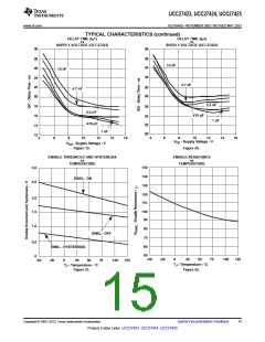
SLUS545D –NOVEMBER 2002–REVISED MAY 2013
Thermal Information
The useful range of a driver is greatly affected by the drive power requirements of the load and the thermal
characteristics of the IC package. In order for a power driver to be useful over a particular temperature range the
package must allow for the efficient removal of the heat produced while keeping the junction temperature within
rated limits. The UCC27423/4/5 family of drivers is available in three different packages to cover a range of
application requirements.
As shown in the power dissipation rating table, the SOIC-8 (D) and PDIP-8 (P) packages each have a power
rating of around 0.5W with TA = 70°C. This limit is imposed in conjunction with the power derating factor also
given in the table. Note that the power dissipation in our earlier example is 0.432W with a 10nF load, 12VDD,
switched at 300kHz. Thus, only one load of this size could be driven using the D or P package, even if the two
onboard drivers are paralleled. The difficulties with heat removal limit the drive available in the older packages.
The MSOP PowerPAD-8 (DGN) package significantly relieves this concern by offering an effective means of
removing the heat from the semiconductor junction. As illustrated in Reference 3, the PowerPAD packages offer
a leadframe die pad that is exposed at the base of the package. This pad is soldered to the copper on the PC
board directly underneath the IC package, reducing the θjc down to 4.7°C/W. Data is presented in Reference 3
to show that the power dissipation can be quadrupled in the PowerPAD configuration when compared to the
standard packages. The PC board must be designed with thermal lands and thermal vias to complete the heat
removal subsystem, as summarized in Reference 4. This allows a significant improvement in heatsinking over
that available in the D or P packages, and is shown to more than double the power capability of the D and P
packages. Note that the PowerPAD™ is not directly connected to any leads of the package. However, it is
electrically and thermally connected to the substrate which is the ground of the device.
References
1. Power Supply Seminar SEM-1400 Topic 2: Design And Application Guide For High Speed MOSFET Gate
Drive Circuits, by Laszlo Balogh, Texas Instruments (SLUP133).
2. Application Note, Practical Considerations in High Performance MOSFET, IGBT and MCT Gate Drive
Circuits, by Bill Andreycak, Texas Instruments ( SLUA105)
3. Technical Brief, PowerPad Thermally Enhanced Package, Texas Instruments (SLMA002)
4. Application Brief, PowerPAD Made Easy, Texas Instruments (SLMA004)
Related Products
PRODUCT
UCC37323/4/5
UCC37321/2
DESCRIPTION
Dual 4-A Low-Side Drivers
PACKAGES
MSOP-8 PowerPAD, SOIC-8, PDIP-8
MSOP-8 PowerPAD, SOIC-8, PDIP-8
TSSOP-8, SOIC-8, PDIP-8
TSSOP-8, SOIC-8, PDIP-8
5-Pin SOT-23
Single 9-A Low-Side Driver with Enable
TPS2811/12/13
TPS2814/15
Dual 2-A Low-Side Drivers with Internal Regulator
Dual 2-A Low-Side Drivers with Two Inputs per Channel
Single 2-A Low-Side Driver with Internal Regulator
Single 2-A Low-Side Driver
TPS2816/17/18/19
TPS2828/29
5-Pin SOT-23
Copyright © 2002–2013, Texas Instruments Incorporated
Submit Documentation Feedback
11
Product Folder Links: UCC27423 UCC27424 UCC27425

 TI [ TEXAS INSTRUMENTS ]