UCC21759-Q1
SLUSEB4A – AUGUST 2020 – REVISED DECEMBER 2020
www.ti.com
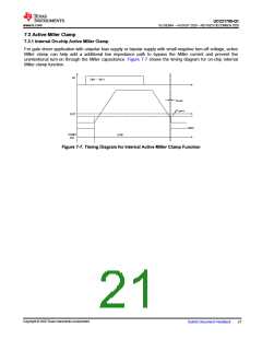
7.3 Active Miller Clamp
7.3.1 Internal On-chip Active Miller Clamp
For gate driver application with unipolar bias supply or bipolar supply with small negative turn-off voltage, active
Miller clamp can help add a additional low impedance path to bypass the Miller current and prevent the
unintentional turn-on through the Miller capacitance. Figure 7-7 shows the timing diagram for on-chip internal
Miller clamp function.
IN
(”IN+‘ Å ”INÅ‘)
tDCLMPI
VCLMPTH
OUT
HIGH
CLMPI
Ctrl.
LOW
Figure 7-7. Timing Diagram for Internal Active Miller Clamp Function
Copyright © 2020 Texas Instruments Incorporated
Submit Document Feedback
21

 TI [ TEXAS INSTRUMENTS ]