UCC21759-Q1
SLUSEB4A – AUGUST 2020 – REVISED DECEMBER 2020
www.ti.com
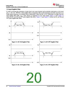
7.2 Input Deglitch Filter
In order to increase the robustness of gate driver over noise transient and accidental small pulses on the input
pins, i.e. IN+, IN–, RST/EN, a 40ns deglitch filter is designed to filter out the transients and make sure there is no
faulty output responses or accidental driver malfunctions. When the IN+ or IN– PWM pulse is smaller than the
input deglitch filter width, TINFIL, there will be no responses on OUT drive signal. Figure 7-3 and Figure 7-4
shows the IN+ pin ON and OFF pulse deglitch filter effect. Figure 7-5 and Figure 7-6 shows the IN– pin ON and
OFF pulse deglitch filter effect.
IN+
tPWM < TINFIL
tPWM < TINFIL
IN+
INÅ
INÅ
OUT
OUT
Figure 7-3. IN+ ON Deglitch Filter
Figure 7-4. IN+ OFF Deglitch Filter
IN+
IN+
INÅ
tPWM < TINFIL
tPWM < TINFIL
INÅ
OUT
OUT
Figure 7-5. IN– ON Deglitch Filter
Figure 7-6. IN– OFF Deglitch Filter
Copyright © 2020 Texas Instruments Incorporated
20
Submit Document Feedback

 TI [ TEXAS INSTRUMENTS ]