TPS929160-Q1
ZHCSNG0 – APRIL 2023
www.ti.com.cn
8.3 Power Supply Recommendations
The TPS929160-Q1 is designed to operate from an automobile electrical power system within the range
specified in Power Supply (SUPPLY) and Power Bias (VBAT). The V(SUPPLY) input must be protected from
the reverse voltage and the voltage dump condition over 40 V. The impedance of the input supply voltage source
must be low enough that the input current transient does not cause the input voltage at the supply pin of device
to drop below LED string required forward voltage. If the input supply is connected with long wires, additional
bulk capacitance is required in addition to normal input capacitor.
8.4 Layout
8.4.1 Layout Guidelines
Thermal dissipation is the primary consideration for TPS929160-Q1 layout. TI recommends that a large thermal
dissipation area should be connected to the thermal pads with multiple thermal vias. Place the capacitor for
SUPPLY input, VBAT input and VLDO output as close as possible to the pins. The R(REF) resistor must also
be placed as close as possible to the REF pin together with 1-nF capacitor for enhanced noise immunity. A
1-nF ceramic capacitor is recommended to be put closely to each of output channels to achieve good EMC
performance.
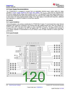
8.4.2 Layout Example
GND
TPS929160-Q1
To µC or CAN Tranceiver
1
2
RX
ADDR3 38
ADDR2 37
ADDR1 36
ADDR0 35
VLDO
GND
TX
3
4
To µC or CAN Tranceiver
To CAN Tranceiver
OUTA0
5
NSTB
REF
34
6
OUTA1 33
OUTB0 32
OUTB1 31
NC 30
7
ERR
EN
GND
GND
8
9
VBAT
SUPPLY
VBAT
10
OUTC0
29
To Power Supply
11 SUPPLY
12 FS1
OUTC1 28
NC 27
13 FS0
OUTD0 26
OUTD1 25
NC 24
14 OUTH1
15 OUTH0
Exposed Pad
16
17
OUTE0 23
OUTE1 22
NC 21
OUTG1
OUTG0
18 NC
19 OUTF1
OUTF0 20
GND
图 8-5. TPS929160-Q1 Layout
Copyright © 2023 Texas Instruments Incorporated
English Data Sheet: SLVSG60
120 Submit Document Feedback
Product Folder Links: TPS929160-Q1

 TI [ TEXAS INSTRUMENTS ]