TPS929160-Q1
ZHCSNG0 – APRIL 2023
www.ti.com.cn
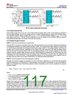
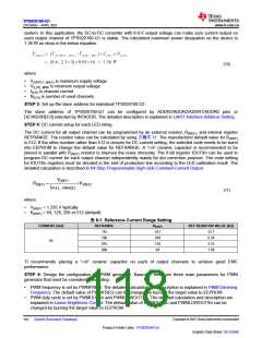
system. In this application, the DC-to-DC converter with 8.6-V output voltage can make sure current output on
each output channel of TPS929160-Q1 is stable. The calculated maximum power dissipation on the device is
1.36 W as show in the below equation.
(10)
where
•
•
•
•
V(SPPLY_MAX) is maximum supply voltage.
V(LED_MIN) is minimum output voltage.
I(CH) is channel current.
N(CH) is number of used channels.
STEP 3: Set up the slave address for individual TPS929160-Q1.
The slave address of TPS929160-Q1 can be configured by ADDR3/ADDR2/ADDR1/ADDR0 pins or
DEVADDR[3:0] selected by INTADDR. The detailed description is explained in UART Interface Address Setting.
STEP 4: DC current setup for each LED string.
The DC current for all output channel can be programmed by an external resistor, R(REF), and internal register
REFRANGE. The resistor value can be calculated by using 方程式 11. The manufacturer default value for K(REF)
is 512. If the other number rather than 512 is chosen for DC current setting, the selected code needs to be burnt
into EEPROM to change the default value for REFRANGE. A 1-nF ceramic capacitor is recommended to be
placed in parallel with R(REF) resistor to improve the noise immunity. The 6-bit register IOUTXn can be used to
program DC current for each output channel independently mainly for dot correction purpose. The code setting
for IOUTXn registers must be decided in the end of production line according to the LED calibration result. The
detailed calculation is described in 64-Step Programmable High-Side Constant-Current Output.
V
(REF)
R(REF)
=
ìK(REF)
I(FULL _RANGE)
(11)
where
•
•
V(REF) = 1.235 V typically.
K(REF) = 64, 128, 256 or 512 (default).
表 8-1. Reference Current Range Setting
CURRENT (mA)
REFRANGE
K(REF)
512
256
128
64
REF RESISTOR VALUE (kΩ)
11b
12.7
6.34
3.16
1.58
10b
50
01b
00b
TI recommends placing a 1-nF ceramic capacitor on each of output channels to achieve good EMC
performance.
STEP 5: Design the configuration for PWM generator. Basically, there are three main parameters for PWM
generator that must be considered, including:
•
•
PWM frequency is set by PWMFREQ. The detailed calculation and description is explained in PWM Dimming
Frequency. The default value of PWMFREQ can be changed by burning the target value to EEPROM.
PWM duty cycle is set by PWMOUTXn and PWMLOWOUTXn. The detailed calculation and description are
explained in Linear Brightness Control. The default value of PWMOUTXn and PWMLOWOUTXn can be
changed by burning the target value to EEPROM.
Copyright © 2023 Texas Instruments Incorporated
English Data Sheet: SLVSG60
118
Submit Document Feedback
Product Folder Links: TPS929160-Q1

 TI [ TEXAS INSTRUMENTS ]