TPS7A39
www.ti.com.cn
ZHCSGP0A –JULY 2017–REVISED SEPTEMBER 2017
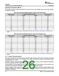
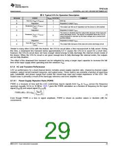
表 6. Typical UVLOx Operation Description
REGION
EVENT
VOUTx STATUS
COMMENT
A
B
Turn-on, |VINx| ≤ |VUVLOx
Regulation
|
0
1
Start-up
Regulates to target VOUTx
Brownout,|VINx| ≥ |VUVLOx
–
C
D
1
1
The output can fall out of regulation but the device is still enabled
Regulates to target VOUTx
VHYSx
|
Regulation
The device is disabled and the output falls because of the load and
active discharge circuit. The device is reenabled when the UVLOx
rising threshold is reached by the input voltage and a normal start-
up then follows.
Brownout, |VINx| < |VUVLOx
VHYSx
–
E
0
|
F
Regulation
1
0
Regulates to target VOUTx
Turn-off, |VINx| < |VUVLOx
–
G
The output falls because of the load and active discharge circuit
VHYSx
|
Similar to many other LDOs with this feature, the UVLOx circuit takes a few microseconds to fully assert. During
this time, a downward line transient below approximately 0.8 V causes the UVLOx to assert for a short time;
however, the UVLOx circuit does not have enough stored energy to fully discharge the internal circuits inside of
the device. When the UVLOx circuit is not given enough time to fully discharge the internal nodes, the outputs
are not fully disabled.
The effect of the downward line transient can be mitigated by using a larger input capacitor to increase the fall
time of the input supply when operating near the minimum VINx
.
8.1.9 AC and Transient Performance
LDO ac performance for a dual-channel device includes power-supply rejection ratio, channel-to-channel output
isolation, output current transient response, and output noise. These metrics are primarily a function of open-loop
gain, bandwidth, and phase margin that control the closed-loop input and output impedance of the LDO. The
output noise is primarily a result of the band-gap reference and error amplifier noise.
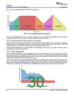
8.1.9.1 Power-Supply Rejection Ratio (PSRR)
PSRR is a measure of how well the LDO control-loop rejects signals from VINx to VOUTx across the frequency
spectrum (usually 10 Hz to 10 MHz). 公式 7 gives the PSRR calculation as a function of frequency for the input
signal [VINx(f)] and output signal [VOUTx(f)].
≈
∆
«
’
÷
◊
V
INx(f)
PSRR (dB) = 20 Log10
VOUTx(f)
(7)
Even though PSRR is a loss in signal amplitude, PSRR is shown as positive values in decibels (dB) for
convenience.
版权 © 2017, Texas Instruments Incorporated
29

 TI [ TEXAS INSTRUMENTS ]