TPS7A39
ZHCSGP0A –JULY 2017–REVISED SEPTEMBER 2017
www.ti.com.cn
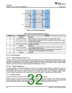
8.1.8 Start-Up
8.1.8.1 Soft-Start Control (NR/SS)
Each output of the device features a user-adjustable, monotonic, voltage-controlled soft-start that is set with an
external capacitor (CNR/SS). This soft-start eliminates power-up initialization problems.
The output voltage (VOUTx) rises proportionally to VNR/SS during start-up. As such, the time required for VNR/SS to
reach its nominal value determines the rise time of VOUTx (start-up time).
The soft-start ramp time depends on the soft-start charging current (INR/SS), the soft-start capacitance (CNR/SS),
and the internal reference (VNR/SS). 公式 5 calculates the approximate soft-start ramp time (tSS):
tSS = RNR/SS × CNR/SS × ln [(VNR/SS + INR/SS × RNR/SS) / (INR/SS×RNR/SS)]
(5)
Values for the soft-start charging currents, RNR/SS, and the device internal CNR/SS are provided in the table.
8.1.8.1.1 In-Rush Current
In-rush current is defined as the current into the LDO at the INx pin during start-up. In-rush current then consists
primarily of the sum of load current and the current used to charge the output capacitor. This current is difficult to
measure because the input capacitor must be removed, which is not recommended. However, the in-rush current
can be estimated by 公式 6:
C
OUTx ´ dVOUTx(t)
VOUTx(t)
RLOAD
IOUTx(t) =
+
dt
where:
•
•
•
VOUTx(t) is the instantaneous output voltage of the turn-on ramp
dVOUTx(t) / dt is the slope of the VOUTx ramp
RLOAD is the resistive load impedance
(6)
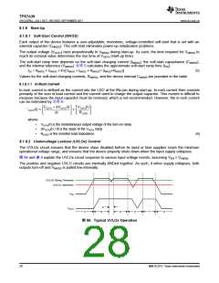
8.1.8.2 Undervoltage Lockout (UVLOx) Control
The UVLOx circuit ensures that the device stays disabled before its input or bias supplies reach the minimum
operational voltage range, and ensures that the device properly shuts down when the input supply collapses.
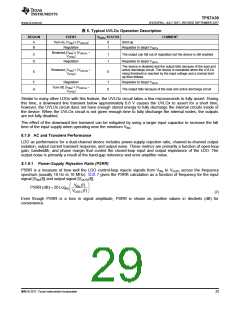
图 66 and 表 6 explain the UVLOx circuit response to various input voltage events, assuming VEN ≥ VIH(EN)
.
The positive and negative UVLO circuits are internally ANDed together. As such, if either supply collapses, both
outputs turn-off and VNR/SS is pulled low internally.
UVLOx Rising Threshold
UVLOx Hysteresis
VINx
C
VOUTx
tAt
tBt
tDt
tEt
tFt
tGt
图 66. Typical UVLOx Operation
28
版权 © 2017, Texas Instruments Incorporated

 TI [ TEXAS INSTRUMENTS ]