TPS79801-Q1, TPS79850-Q1
SLVS822D –MARCH 2009–REVISED AUGUST 2011
www.ti.com
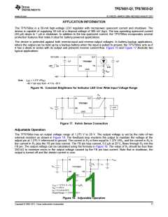
A 100-pF capacitor (C1) placed in parallel with the top resistor (R2) of the output divider is necessary for stability
and transient performance of the adjustable TPS798xx. The impedance of C1 at 10 kHz should be less than the
value of R2.
The adjustable device is tested and specified with the FB pin tied to the OUT pin and a 1 mA dc load (unless
otherwise specified) for an output voltage of 1.275 V. Specifications for output voltages greater than 1.275 V are
proportional to the ratio of the desired output voltage to 1.275 V (VOUT/1.275 V). For example, load regulation for
an output current change of 1 mA to 50 mA is –10 mV (typ) at VOUT = 1.275 V.
At VOUT = 12 V, load regulation is:
(12 V/1.275 V) × (–10 mV) = –94 mV
Output Capacitance and Transient Response
The TPS798xx is designed to be stable with a wide range of output capacitors. The ESR of the output capacitor
affects stability, most notably with small capacitors. A minimum output capacitor of 1 μF with an ESR of 3 Ω or
less is recommended to prevent oscillations. The TPS798xx is a micropower device, and output transient
response is a function of output capacitance. Larger values of output capacitance decrease the peak deviations
and provide improved transient response for larger load current changes. Bypass capacitors, used to decouple
individual components powered by the TPS798xx, increase the effective output capacitor value.
Extra consideration must be given to the use of ceramic capacitors. Ceramic capacitors are manufactured with a
variety of dielectrics, each with different behavior over temperature and applied voltage. The most common
dielectrics used are Z5U, Y5 V, X5R, and X7R. The Z5U and Y5 V dielectrics are good for providing high
capacitances in a small package, but exhibit strong voltage and temperature coefficients. When used with a 5 V
regulator, a 10μF Y5 V capacitor can exhibit an effective value as low as 1μF to 2μF over the operating
temperature range. The X5R and X7R dielectrics result in more stable characteristics and are more suitable for
use as the output capacitor. The X7R type has better stability across temperature, while the X5R is less
expensive and is available in higher values.
Voltage and temperature coefficients are not the only sources of problems. Some ceramic capacitors have a
piezoelectric response. A piezoelectric device generates voltage across its terminals because of mechanical
stress, similar to the way a piezoelectric accelerometer or microphone works. For a ceramic capacitor, the stress
can be induced by vibrations in the system or thermal transients.
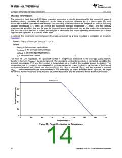
Thermal Considerations
The power handling capability of the device is limited by the maximum rated junction temperature (125°C). The
power dissipated by the device consists of two components:
•
•
Output current multiplied by the input/output voltage differential: IOUT × (VIN – VOUT
GND pin current multiplied by the input voltage: IGND × VIN
)
The GND pin current can be found by examining the GND pin current curves in the Typical
Characteristics . Power dissipation is equal to the sum of the two components listed previously.
The TPS798xx series regulators have internal thermal limiting designed to protect the device during overload
conditions. Do not exceed the maximum junction temperature rating of 125°C. It is important to give careful
consideration to all sources of thermal resistance from junction to ambient. Additional heat sources mounted
nearby must also be considered.
For surface-mount devices, heat sinking is accomplished by using the heat-spreading capabilities of the printed
circuit board (PCB) and its copper traces. Copper board stiffeners and plated through-holes can also be used to
spread the heat generated by power devices.
12
Copyright © 2009–2011, Texas Instruments Incorporated

 TI [ TEXAS INSTRUMENTS ]