TPS61020, TPS61024, TPS61025
TPS61026, TPS61027, TPS61028
TPS61029
www.ti.com
SLVS451D–SEPTEMBER 2003–REVISED FEBRUARY 2006
V
V
BAT
BAT
R1 + R2
* 1 + 390 kW
* 1
ǒ
Ǔ ǒ Ǔ
V
500 mV
LBI*threshold
(3)
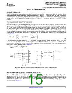
The output of the low battery supervisor is a simple open-drain output that goes active low if the dedicated
battery voltage drops below the programmed threshold voltage on LBI. The output requires a pullup resistor with
a recommended value of 1 MΩ. If not used, the LBO pin can be left floating or tied to GND.
INDUCTOR SELECTION
A boost converter normally requires two main passive components for storing energy during the conversion. A
boost inductor and a storage capacitor at the output are required. To select the boost inductor, it is
recommended to keep the possible peak inductor current below the current limit threshold of the power switch in
the chosen configuration. For example, the current limit threshold of the TPS6102xs switch is 1800 mA at an
output voltage of 5 V. The highest peak current through the inductor and the switch depends on the output load,
the input (VBAT), and the output voltage (VOUT). Estimation of the maximum average inductor current can be
done using Equation 4:
V
OUT
0.8
I
+ I
L
OUT
V
BAT
(4)
For example, for an output current of 200 mA at 3.3 V, at least 920 mA of average current flows through the
inductor at a minimum input voltage of 0.9 V.
The second parameter for choosing the inductor is the desired current ripple in the inductor. Normally, it is
advisable to work with a ripple of less than 20% of the average inductor current. A smaller ripple reduces the
magnetic hysteresis losses in the inductor, as well as output voltage ripple and EMI. But in the same way,
regulation time at load changes rises. In addition, a larger inductor increases the total system costs. With those
parameters, it is possible to calculate the value for the inductor by using Equation 5:
ǒVOUT BATǓ
V
–V
BAT
L +
DI ƒ V
L
OUT
(5)
Parameter f is the switching frequency and ∆IL is the ripple current in the inductor, i.e., 20% × IL. In this example,
the desired inductor has the value of 5.5 µH. With this calculated value and the calculated currents, it is possible
to choose a suitable inductor. In typical applications a 6.8 µH inductance is recommended. The device has been
optimized to operate with inductance values between 2.2 µH and 22 µH. Nevertheless operation with higher
inductance values may be possible in some applications. Detailed stability analysis is then recommended. Care
has to be taken that load transients and losses in the circuit can lead to higher currents as estimated in
Equation 5. Also, the losses in the inductor caused by magnetic hysteresis losses and copper losses are a major
parameter for total circuit efficiency.
The following inductor series from different suppliers have been used with the TPS6102x converters:
Table 1. List of Inductors
VENDOR
INDUCTOR SERIES
CDRH4D28
CDRH5D28
7447789
Sumida
Wurth Elektronik
744042
EPCOS
B82462-G4
SD25
Cooper Electronics Technologies
SD20
16
Submit Documentation Feedback

 TI [ TEXAS INSTRUMENTS ]