TPS61020, TPS61024, TPS61025
TPS61026, TPS61027, TPS61028
TPS61029
www.ti.com
SLVS451D–SEPTEMBER 2003–REVISED FEBRUARY 2006
DETAILED DESCRIPTION (continued)
Undervoltage Lockout
An undervoltage lockout function prevents device start-up if the supply voltage on VBAT is lower than
approximately 0.8 V. When in operation and the battery is being discharged, the device automatically enters the
shutdown mode if the voltage on VBAT drops below approximately 0.8 V. This undervoltage lockout function is
implemented in order to prevent the malfunctioning of the converter.
Softstart and Short Circuit Protection
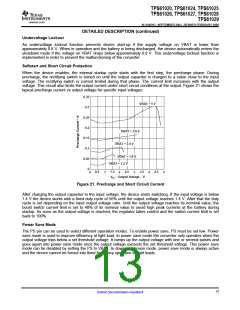
When the device enables, the internal startup cycle starts with the first step, the precharge phase. During
precharge, the rectifying switch is turned on until the output capacitor is charged to a value close to the input
voltage. The rectifying switch is current limited during that phase. The current limit increases with the output
voltage. This circuit also limits the output current under short circuit conditions at the output. Figure 21 shows the
typical precharge current vs output voltage for specific input voltages:
0.35
VBAT = 5 V
0.3
0.25
0.2
VBAT = 3.6 V
0.15
VBAT = 2.4 V
0.1
VBAT = 1.8 V
0.05
VBAT = 1.2 V
0
0
1.5
0.5
2.5
3.5
4.5
1
2
3
4
5
V
O
− Output Voltage − V
Figure 21. Precharge and Short Circuit Current
After charging the output capacitor to the input voltage, the device starts switching. If the input voltage is below
1.4 V the device works with a fixed duty cycle of 50% until the output voltage reaches 1.4 V. After that the duty
cycle is set depending on the input output voltage ratio. Until the output voltage reaches its nominal value, the
boost switch current limit is set to 40% of its nominal value to avoid high peak currents at the battery during
startup. As soon as the output voltage is reached, the regulator takes control and the switch current limit is set
back to 100%.
Power Save Mode
The PS pin can be used to select different operation modes. To enable power save, PS must be set low. Power
save mode is used to improve efficiency at light load. In power save mode the converter only operates when the
output voltage trips below a set threshold voltage. It ramps up the output voltage with one or several pulses and
goes again into power save mode once the output voltage exceeds the set threshold voltage. This power save
mode can be disabled by setting the PS to VBAT. In down conversion mode, power save mode is always active
and the device cannot be forced into fixed frequency operation at light loads.
13
Submit Documentation Feedback

 TI [ TEXAS INSTRUMENTS ]