TPS55340
www.ti.com
SLVSBD4 –MAY 2012
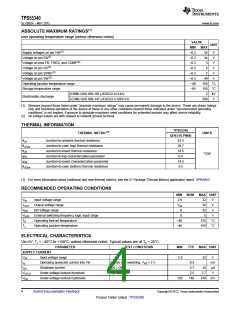
ELECTRICAL CHARACTERISTICS (continued)
Vin=5V, TJ = –40°C to +150°C, unless otherwise noted. Typical values are at TA = 25°C.
PARAMETER
TEST CONDITIONS
MIN
TYP
MAX UNIT
ENABLE AND REFERENCE CONTROL
VEN
EN threshold voltage
EN rising input
0.9
0.1
1.08
0.16
950
1.0
1.30
0.22
1600
V
V
VENh
REN
EN threshold hysteresis
EN pull down resistor
400
kΩ
ms
Toff
Shutdown delay, SS discharge
SYN logic high voltage
SYN logic low voltage
EN high to low
VSYNh
VSYNl
1.2
0.4
V
VOLTAGE AND CURRENT CONTROL
1.204 1.229 1.254
1.220 1.229 1.238
VREF
Voltage feedback regulation voltage
V
TA = 25°C
IFB
Voltage feedback input bias current
Comp pin sink current
TA = 25°C
1.6
42
42
20
nA
µA
µA
Isink
VFB = VREF+200 mV, VCOMP = 1 V
VFB = VREF–200 mV, VCOMP = 1 V
Isource
Comp pin source current
High Clamp, VFB = 1 V
Low Clamp, VFB = 1.5 V
3.1
0.75
VCCLP
Comp pin Clamp Voltage
V
V
VCTH
Gea
Rea
fea
Comp pin threshold
Duty cycle = 0%
1.04
360
10
Error amplifier transconductance
Error amplifier output resistance
Error amplifier crossover frequency
240
440 µmho
MΩ
500
kHz
FREQUENCY
RFREQ = 480 kΩ
75
460
920
89%
94
577
130
fSW
Frequency
RFREQ = 80 kΩ
740 kHz
1480
RFREQ = 40 kΩ
1140
96%
1.25
77
Dmax
Maximum duty cycle
FREQ pin voltage
VFB = 1.0 V, RFREQ = 80 kΩ
VFREQ
Tmin_on
V
Minimum on pulse width
RFREQ = 80 kΩ
ns
POWER SWITCH
VIN = 5 V
VIN = 3 V
60
70
110
mΩ
120
RDS(ON)
N-channel MOSFET on-resistance
ILN_NFET
OCP and SS
ILIM
N-channel leakage current
VDS = 25 V, TA = 25°C
2.1
µA
N-Channel MOSFET current limit
Soft-start bias current
D = Dmax
Vss = 0 V
5.25
6.6
6
7.75
A
ISS
µA
THERMAL SHUTDOWN
Tshutdown Thermal shutdown threshold
Thysteresis Thermal shutdown threshold hysteresis
165
15
°C
°C
Copyright © 2012, Texas Instruments Incorporated
Submit Documentation Feedback
5
Product Folder Link(s) :TPS55340

 TI [ TEXAS INSTRUMENTS ]