TPS55340
SLVSBD4 –MAY 2012
www.ti.com
These devices have limited built-in ESD protection. The leads should be shorted together or the device placed in conductive foam
during storage or handling to prevent electrostatic damage to the MOS gates.
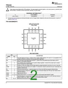
ORDERING INFORMATION(1)
TJ
PART NUMBER
PACKAGE
-40°C to 150°C
TPS55340RTE
QFN-16
(1) For the most current package and ordering information see the Package Option Addendum at the end of this document, or see the TI
website at www.ti.com.
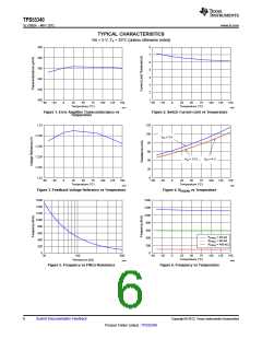
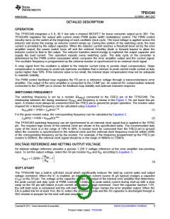
PIN ASSIGNMENTS
QFN-16 PACKAGE
(Top View)
16
15
14
13
1
SW
VIN
EN
SS
12
PGND
2
3
4
11
10
9
PGND
NC
PowerPAD
(17)
FREQ
5
6
7
8
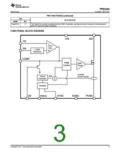
PIN FUNCTIONS
PIN
DESCRIPTION
NAME
VIN
NO.
2
The input supply pin to the IC. Connect VIN to a supply voltage between 2.9V and 32V. It is acceptable for the
voltage on the pin to be different from the boost power stage input.
SW
FB
1, 15, 16
8
SW is the drain of the internal power MOSFET. Connect SW to the switched side of the boost or SEPIC
inductor or the flyback transformer.
Error amplifier input and feedback pin for positive voltage regulation. Connect to the center tap of a resistor
divider to program the output voltage.
EN
3
7
Enable pin. When the voltage of this pin falls below the enable threshold for more than 1ms, the IC turns off.
COMP
Output of the transconductance error amplifier. An external RC network connected to this pin compensates the
regulator feedback loop.
SS
4
9
Soft-start programming pin. A capacitor between the SS pin and AGND pin programs soft-start timing.
FREQ
Switching frequency program pin. An external resistor connected between the FREQ pin and AGND sets the
switching frequency.
AGND
PGND
SYNC
6
Signal ground of the IC.
11, 12, 13 Power ground of the IC. It is connected to the source of the internal power MOSFET switch.
5
Switching frequency synchronization pin. An external clock signal can be used to set the switching frequency
between 200kHz and 1.0MHz. If not used, this pin should be tied to AGND.
NC
10, 14
Reserved pin that must be connected to ground.
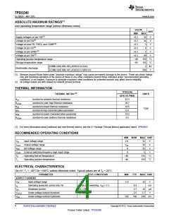
2
Copyright © 2012, Texas Instruments Incorporated

 TI [ TEXAS INSTRUMENTS ]