TPS40200-Q1
SLUS739D –SEPTEMBER 2006–REVISED JULY 2011
www.ti.com
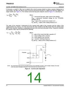
If necessary, a small R-C filter can be added to the current sensing network to reduce nuisance tripping due to
noise pickup. This filter can also be used to trim the overcurrent trip point to a higher level with the addition of a
single resistor (see Figure 31). The nominal overcurrent trip point using the circuit of Figure 31 is described as:
VILIM RF1 + RF2
´
IOC
Where:
IOC = overcurrent trip point, peak current in the inductor
=
RILIM
RF2
VILIM = overcurrent threshold voltage for the TPS40200,
typically 100 mV
RILIM = value of the current sense resistor in Ω
RF1 and RF2 = values of the scaling resistors in Ω
The value of the capacitor is determined by the nominal pulse width of the converter and the values of the
scaling resistors RF1 and RF2. It is best not to have the time constant of the filter longer than the nominal pulse
width of the converter, otherwise a substantial increase in the overcurrent trip point occurs. Using this constraint,
the capacitor value may be bounded by the following:
VO
R
f1 ´ Rf2
Cf £
Where:
Cf = value of the current limit filter capacitor in F
÷
Rf1 + Rf2
VIN ´ fSW
VO = output voltage of the converter
VIN = input voltage to the converter
fSW = converter switching frequency
Rf1 and Rf2 = values of the scaling resistors in Ω
VIN
RILIM
RF1
TPS40200
8
7
6
VDD
ISNS
RF2
CF
GDRV
NOTE: The current-limit resistor and its associated circuitry can be eliminated, and pins 7 and 8 shorted. However, the result
of this may result in damage to the part or PCB in the event of an overcurrent event.
Figure 31. Current-Limit Adjustment
14
Copyright © 2006–2011, Texas Instruments Incorporated

 TI [ TEXAS INSTRUMENTS ]