TPS40200-Q1
www.ti.com
SLUS739D –SEPTEMBER 2006–REVISED JULY 2011
Current-Limit Resistor Selection
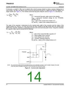
As shown in Figure 31, a resistor in series with the power MOSFET sets the overcurrent protection level. Use a
low-inductance resistor to avoid problems with ringing signals and nuisance tripping. When the FET is on and the
controller senses 100 mV or more drop from the VDD pin to the ISNS pin, an overcurrent condition is declared.
When this happens, the FET is turned off and, as shown in Figure 30, the soft-start capacitor is discharged.
When the soft-start capacitor reaches a level below 150 mV, the converter clears the overcurrent condition flag
and attempts to restart. If the condition that caused the overcurrent event to occur is still present on the output of
the converter (see Figure 29), another overcurrent condition is declared and the process repeats indefinitely.
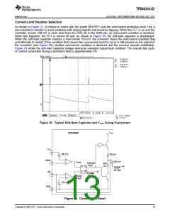
Figure 29 shows the soft-start capacitor voltage during an extended output fault condition. The overall duty cycle
of current conduction during a persistent fault is approximately 2%.
Figure 29. Typical Soft-Start Capacitor and VOUT During Overcurrent
VS-S
TPS40200
VIN
8
7
100 mV
100 kW
+
+
ISNS
300 mV
+
Fault
Latched
Fault
300
kW
S
R
Q
Q
EAMP
SS Ref
SS
Enable
EAMP
2
5
Reset
Fault
+
150 mV
+
GND
Figure 30. Current-Limit Reset
Copyright © 2006–2011, Texas Instruments Incorporated
13

 TI [ TEXAS INSTRUMENTS ]