TPS40200-Q1
www.ti.com
SLUS739D –SEPTEMBER 2006–REVISED JULY 2011
GENERAL INFORMATION
Overview
The TPS40200 is a nonsynchronous controller with a built-in 200-mA driver designed to drive high-speed
P-channel FETs up to 500 kHz. Its small size combined with complete functionality makes the part both versatile
and easy to use.
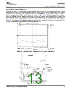
The controller uses a low-value current-sensing resistor in series with the input voltage and the power FET’s
source connection to detect switching current. When the voltage drop across this resistor exceeds 100 mV, the
part enters a hiccup fault mode at approximately 2% of the operating frequency.
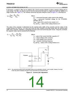
The part uses voltage feedback to an error amplifier that is biased by a precision 700-mV reference.
Feed-forward compensation from the input keeps the PWM gain constant over the full input voltage range,
eliminating the need to change frequency compensation for different input voltages.
The part also incorporates a soft-start feature, during which the output follows a slowly rising soft-start voltage,
preventing output-voltage overshoot.
Programming the Operating Frequency
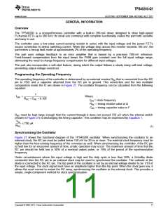
The operating frequency of the controller is determined by an external resistor RRC that is connected from the RC
pin to VDD and a capacitor attached from the RC pin to ground. This connection and the two oscillator
comparators inside the IC are shown in Figure 27. The oscillator frequency can be calculated from the following
equation:
1
fSW
=
Where:
fSW = clock frequency
RRC ´ CRC ´ 0.105
RRC = timing resistor value in Ω
CRC = timing capacitor value in F
RRC must be kept large enough that the current through it does not exceed 750 μA when the internal switch
(shown in Figure 27) is discharging the timing capacitor. This condition may be expressed by Equation 1:
VIN
£ 750 mA
RRC
(1)
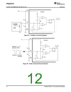
Synchronizing the Oscillator
Figure 27 shows the functional diagram of the TPS40200 oscillator. When synchronizing the oscillator to an
external clock, the RC pin must be pulled below 150 mV for 20 ns or more. The external clock frequency must be
higher than the free-running frequency of the converter as well. When synchronizing the controller, if the RC pin
is held low for an excessive amount of time, erratic operation may occur. The maximum amount of time that the
RC pin should be held low is 50% of a nominal output pulse, or 10% of the period of the synchronization
frequency.
Under circumstances where the input voltage is high and the duty cycle is less than 50%, a Schottky diode
connected from the RC pin to an external clock may be used to synchronize the oscillator. The cathode of the
diode is connected to the RC pin. The trip point of the oscillator is set by an internal voltage divider to be 1/10 of
the input voltage. The clock signal must have an amplitude higher than this trip point. When the clock goes low, it
allows the reset current to restart the RC ramp, synchronizing the oscillator to the external clock. This provides a
simple, single-component method for clock synchronization.
Copyright © 2006–2011, Texas Instruments Incorporated
11

 TI [ TEXAS INSTRUMENTS ]