TPS2148
TPS2158
SLVS373 – AUGUST 2001
APPLICATION INFORMATION
USB power distribution requirements
USB can be implemented in several ways, and, regardless of the type of USB device being developed, several
power-distribution features must be implemented.
•
Hosts/self-powered hubs must:
–
–
Current-limit downstream ports
Report overcurrent conditions on USB V
BUS
Bus-powered hubs must:
–
–
–
Enable/disable power to downstream ports
Power up at <100 mA
Limit inrush current (<44 Ω and 10 µF)
Functions must:
–
–
Limit inrush currents
Power up at <100 mA
USB applications
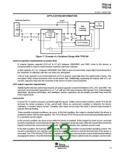
Figure 17 shows the TPS2148 being used in a USB bus-powered peripheral design. The internal 3.3-V LDO
is used to provide power for the USB function controller as well as to the 1.5-kΩ pullup resistor.
Switch 1 provides power to the 5-V circuitry which is only enabled after enumeration is complete to ensure
meeting the 100-mA USB power up requirement. Switch 2 provides power to the 3.3-V circuitry. Switch 2 is also
enabled only after enumeration is complete to satisfy the 100 mA requirement.
16
www.ti.com

 TI [ TEXAS INSTRUMENTS ]