TPS2148
TPS2158
SLVS373 – AUGUST 2001
APPLICATION INFORMATION
Upstream Data Port
D+
1.5 kΩ
5-V
Circuitry
USB
Function
Controller
D–
GND
TPS2148
3.3 V
LDO
5 V
4.7 µF
0.1 µF
10 µF
0.1 µF
3.3 V Circuitry
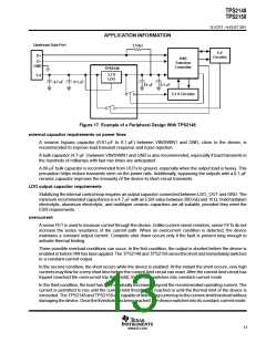
Figure 17. Example of a Peripheral Design With TPS2148
external capacitor requirements on power lines
A ceramic bypass capacitor (0.01-µF to 0.1-µF) between VIN/SWIN1 and GND, close to the device, is
recommended to improve load transient response and noise rejection.
A bulk capacitor (4.7-µF ) between VIN/SWIN1 and GND is also recommended, especially if load transients in
the hundreds of milliamps with fast rise times are anticipated.
A 66-µF bulk capacitor is recommended from OUTx to ground, especially when the output load is heavy. This
precaution helps reduce transients seen on the power rails. Additionally, bypassing the outputs with a 0.1-µF
ceramic capacitor improves the immunity of the device to short-circuit transients.
LDO output capacitor requirements
Stabilizing the internal control loop requires an output capacitor connected between LDO_OUT and GND. The
minimum recommended capacitance is a 4.7 µF with an ESR value between 200 mΩ and 10 Ω. Solid tantalum
electrolytic, aluminum electrolytic, and multilayer ceramic capacitors are all suitable, provided they meet the
ESR requirements.
overcurrent
A sense FET is used to measure current through the device. Unlike current-sense resistors, sense FETs do not
increase the series resistance of the current path. When an overcurrent condition is detected, the device
maintains a constant output current. Complete shut down occurs only if the fault is present long enough to
activate thermal limiting.
Three possible overload conditions can occur. In the first condition, the output is shorted before the device is
enabledorbeforeVINhasbeenapplied. TheTPS2148andTPS2158sensetheshortandimmediatelyswitches
to a constant-current output.
In the second condition, the short occurs while the device is enabled. At the instant the short occurs, very high
currents may flow for a very short time before the current-limit circuit can react. After the current-limit circuit has
tripped (reached the overcurrent trip threshold), the device switches into constant-current mode.
In the third condition, the load has been gradually increased beyond the recommended operating current. The
current is permitted to rise until the current-limit threshold is reached or until the thermal limit of the device is
exceeded. TheTPS2148andTPS2158arecapableofdeliveringcurrentuptothecurrent-limitthresholdwithout
damagingthedevice. Oncethethresholdhasbeenreached, thedeviceswitchesintoitsconstant-currentmode.
13
www.ti.com

 TI [ TEXAS INSTRUMENTS ]