TPS20xxC, TPS20xxC-2
SLVSAU6G –JUNE 2011–REVISED JULY 2013
www.ti.com
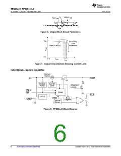
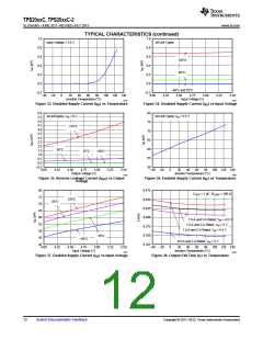
TYPICAL CHARACTERISTICS
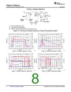
IOUT
VIN
VOUT
OUT
IN
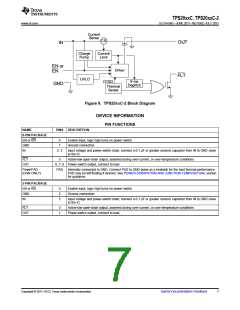
OUT1
IN1
OUT1
VIN
RLOAD
680mF3
Enable
Signal
2
3.01kW2
EN or
EN
FLT
Fault Signal
Pad1 GND
(1) Not every package has all pins
(2) These parts are for test purposes
(3) Helps with output shorting tests when external supply is used.
Figure 10. Test Circuit for System Operation in Typical Characteristics Section
9
8
2.00
1.75
1.50
1.25
1.00
0.75
0.50
0.25
0.00
−0.25
−0.50
9
8
2.00
1.75
1.50
1.25
1.00
0.75
0.50
0.25
0.00
−0.25
−0.50
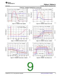
VIN = 5 V, COUT = 150 µF, RLOAD = 5 Ω, TPS2065C
VIN = 5 V, COUT = 150 µF, RLOAD = 100 Ω, TPS2065C
Output Current
Output Current
7
7
Output Voltage
FLT
6
6
FLT
5
5
4
4
EN
3
3
EN
2
2
1
1
Output Voltage
0
0
−1
−2m
−1
−2m
0
2m 4m 6m 8m 10m 12m 14m 16m 18m 20m
0
2m 4m 6m 8m 10m 12m 14m 16m 18m 20m
Time (s)
Time (s)
G001
G002
Figure 11. TPS2065C Output Rise / Fall 5Ω
Figure 12. TPS2065C Output Rise / Fall 100Ω
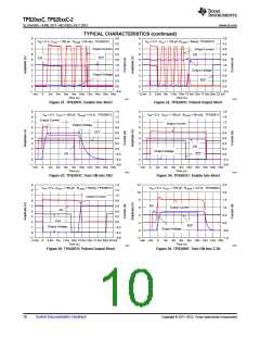
9
8
2.00
1.75
1.50
1.25
1.00
0.75
0.50
0.25
0.00
−0.25
−0.50
9
8
2.00
1.80
1.50
1.20
1.00
0.75
0.50
0.25
0.00
−0.25
−0.50
VIN = 5 V, COUT = 150 µF, RLOAD = 0 Ω, TPS2065C
VIN = 5 V,COUT = 150 µF,RLOAD = 50 mΩ, TPS2065C
7
7
Output Current
EN
6
6
FLT
Output Current
5
5
4
4
FLT
3
3
EN
2
2
Output Voltage
1
1
0
0
Output Voltage
−1
−2m
−1
−2.5m
0
2m 4m 6m 8m 10m 12m 14m 16m 18m
Time (s)
2.5m
7.5m
12.5m
Time (s)
17.5m
22.5m25m
G003
G004
Figure 13. TPS2065C Enable into Output Short
Figure 14. TPS2065C Pulsed Short Applied
8
Submit Documentation Feedback
Copyright © 2011–2013, Texas Instruments Incorporated

 TI [ TEXAS INSTRUMENTS ]