TPS20xxC, TPS20xxC-2
www.ti.com
SLVSAU6G –JUNE 2011–REVISED JULY 2013
ELECTRICAL CHARACTERISTICS: –40°C ≤ TJ ≤ 125°C (continued)
Unless otherwise noted:4.5 V ≤ VIN ≤ 5.5 V, VEN = VIN or VEN = GND, IOUT = 0 A, typical values are at 5 V and 25°C. See the
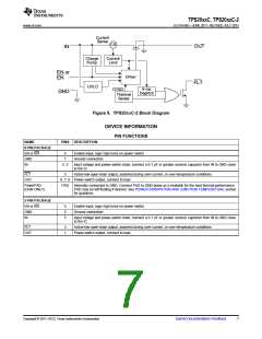
DEVICE INFORMATION table for the rated current of each part number.
PARAMETER
TEST CONDITIONS(1)
MIN
TYP
MAX
UNIT
VIN = 5 V (see Figure 7),
One-half full load → RSHORT = 50 mΩ,
Measure from application to when current falls below 120% of
final value
tIOS
Short-circuit response time(3)
2
µs
SUPPLY CURRENT
ISD Supply current, switch disabled
ISE
IOUT = 0 A
IOUT = 0 A
0.01
65
10
90
µA
µA
Supply current, switch enabled
Leakage current
VOUT = 0 V, VIN = 5 V, disabled,
TPS20XXC-2
Ilkg
0.05
0.2
µA
µA
measure IVIN
IREV
Reverse leakage current
VOUT = 5.5 V, VIN = 0 V, measure IVOUT
20
4
UNDERVOLTAGE LOCKOUT
VUVLO
Rising threshold
Hysteresis(3)
VIN
↑
↓
3.5
3.75
0.14
V
V
VIN
FLT
Output low voltage, FLT
Off-state leakage
FLT deglitch
IFLT = 1 mA
0.2
1
V
VFLT = 5.5 V
µA
ms
tFLT
FLT assertion or deassertion deglitch
6
9
12
OUTPUT DISCHARGE
VIN = 4 V, VOUT = 5 V, disabled
VIN = 5 V, VOUT = 5 V, disabled
TPS20XXC
TPS20XXC
350
300
560
470
1200
800
RPD
Output pull-down resistance
Ω
THERMAL SHUTDOWN
In current limit
135
155
Rising threshold (TJ)
Not in current limit
°C
(4)
Hysteresis
20
(3) These parameters are provided for reference only, and do not constitute part of TI's published device specifications for purposes of TI's
product warranty.
(4) These parameters are provided for reference only, and do not constitute part of TI's published device specifications for purposes of TI's
product warranty.
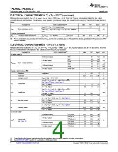
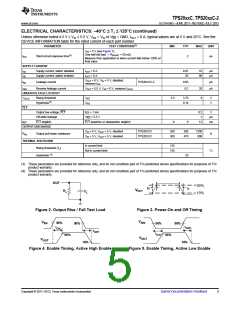
OUT
90%
tR
tF
VOUT
R
C
L
L
10%
Figure 2. Output Rise / Fall Test Load
Figure 3. Power-On and Off Timing
V
V
/EN
50%
EN
50%
50%
50%
t
t
OFF
ON
t
OFF
t
ON
90%
90%
V
OUT
V
OUT
10%
10%
Figure 4. Enable Timing, Active High Enable
Figure 5. Enable Timing, Active Low Enable
Copyright © 2011–2013, Texas Instruments Incorporated
Submit Documentation Feedback
5

 TI [ TEXAS INSTRUMENTS ]