TPS20xxC, TPS20xxC-2
www.ti.com
SLVSAU6G –JUNE 2011–REVISED JULY 2013
The TPS20xxC and TPS20xxC-2 thermal cycles if an overload condition is present long enough to activate
thermal limiting in any of the above cases. This is due to the relatively large power dissipation [(VIN – VOUT) x IOS
]
driving the junction temperature up. The device turns off when the junction temperature exceeds 135°C (min)
while in current limit. The device remains off until the junction temperature cools 20°C and then restarts.
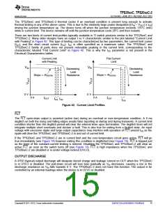
There are two kinds of current limit profiles typically available in TI switch products similar to the TPS20xxC and
TPS20xxC-2. Many older designs have an output I vs V characteristic similar to the plot labeled "Current Limit
with Peaking" in Figure 42. This type of limiting can be characterized by two parameters, the current limit corner
(IOC), and the short circuit current (IOS). IOC is often specified as a maximum value. The TPS20xxC and
TPS20xxC-2 family of parts does not present noticeable peaking in the current limit, corresponding to the
characteristic labeled "Flat Current Limit" in Figure 42. This is why the IOC parameter is not present in the
Electrical Characteristics tables.
Current Limit
with Peaking
Flat Current
Limit
VIN
VIN
Decreasing
Load
Resistance
Decreasing
Load
Resistance
Slope = -RDS(ON)
Slope = -RDS(ON)
0 V
0 V
0 A
0 A
IOUT
IOUT
IOS IOC
IOS
Figure 42. Current Limit Profiles
FLT
The FLT open-drain output is asserted (active low) during an overload or over-temperature condition. A 9 ms
deglitch on both the rising and falling edges avoids false reporting at startup and during transients. A current limit
condition shorter than the deglitch period will clear the internal timer upon termination. The deglitch timer will not
integrate multiple short overloads and declare a fault. This is also true for exiting from a faulted state. An input
voltage with excessive ripple and large output capacitance may interfere with operation of FLT around IOS as the
ripple will drive the TPS20xxC and TPS20xxC-2 in and out of current limit.
If the TPS20xxC and TPS20xxC-2 are in current limit and the over-temperature circuit goes active, FLT will go
true immediately (see Figure 14) however exiting this condition is deglitched (see Figure 16). FLT is tripped just
as the knee of the constant-current limiting is entered. Disabling the TPS20xxC and TPS20xxC-2 will clear an
active FLT as soon as the switch turns off (see Figure 13). FLT is high impedance when the TPS20xxC and
TPS20xxC-2 are disabled or in under-voltage lockout (UVLO).
OUTPUT DISCHARGE
A 470Ω (typical) output discharge will dissipate stored charge and leakage current on OUT when the TPS20xxC
is in UVLO or disabled. The pull-down circuit will lose bias gradually as VIN decreases, causing a rise in the
discharge resistance as VIN falls towards 0 V. The TPS20xxC-2 does not have this function. The output is be
controlled by an external loadings when the device is in ULVO or disabled.
Copyright © 2011–2013, Texas Instruments Incorporated
Submit Documentation Feedback
15

 TI [ TEXAS INSTRUMENTS ]