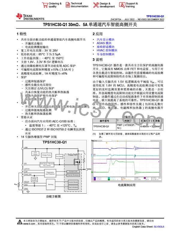
TPS1HC30-Q1
ZHCSP75A –JULY 2022 –REVISED DECEMBER 2022
www.ti.com.cn
6.5 Electrical Characteristics (continued)
VBB = 6 V to 28 V, TA = –40°C to 125°C (unless otherwise noted); Typical application is 13.5 V, 10 Ω, RILIM=Open (unless
otherwise specified)
PARAMETER
TEST CONDITIONS
MIN
TYP
2.2
14
MAX
UNIT
µA
IIL, LATCH
IIH, LATCH
Input current low-level
Input current high-level
VLATCH = 0.8 V
VLATCH = 5 V
µA
(1) Current limit regulation value will vary with increase of VDS voltage. For more information, see 节8.3.2
6.6 SNS Timing Characteristics
VBB = 6 V to 18 V, TJ = –40°C to +150°C (unless otherwise noted)
PARAMETER
TEST CONDITIONS
MIN
TYP
MAX
UNIT
SNS TIMING - CURRENT SENSE
VENx= 5 V, VDIA_EN = 0 V to 5 V
RSNS = 1 kΩ, IL = 1A
30
30
µs
µs
Settling time from rising edge of DIA_EN
50% of VDIA_EN to 90% of settled ISNS
tSNSION1
VEN = 5 V, VDIA_EN = 0 V to 5 V
RSNS = 1 kΩ, IL = 30 mA
VEN = VDIA_EN = 0 V to 5 V
VBB = 13.5 V RSNS = 1 kΩ, RLOAD
10 Ω
Settling time from rising edge of EN and
DIA_EN
50% of VDIA_EN VEN to 90% of settled ISNS
tSNSION2
tSNSION3
tSNSIOFF
=
150
150
20
µs
µs
µs
VEN = 0 V to 5 V, VDIA_EN = 5 V VBB =
13.5 V
RSNS = 1 kΩ, RLOAD = 10 Ω
Settling time from rising edge of EN with
DIA_EN HI;
50% of VDIA_EN VEN to 90% of settled ISNS
VEN = 5 V, VDIA_EN = 5 V to 0 V VBB
= 13.5 V
Settling time from falling edge of DIA_EN
RSNS = 1 kΩ, RL = 10 Ω
VEN = 5 V, VDIA_EN = 5 V
RSNS = 1 kΩ, IOUT = 0.5 A to 3 A
tSETTLEH
tSETTLEL
Settling time from rising edge of load step
Settling time from falling edge of load step
20
20
µs
µs
VEN = 5 V, VDIA_EN = 5 V
RSNS = 1 kΩ, IOUT = 3 A to 0.5 A
6.7 Switching Characteristics
VBB = 13.5 V, TJ = –40°C to +150°C (unless otherwise noted)
PARAMETER
TEST CONDITIONS
MIN
TYP
MAX
UNIT
Channel Turn-on delay time (from
Standby)
VBB = 13.5 V, RL = 10 Ω50% of EN
to 10% of VOUT
tDR
tDR
tDF
10
40
35
55
µs
Channel Turn-on delay time (from
Active)
VBB = 13.5 V, RL = 10 Ω50% of EN
to 10% of VOUT
10
10
45
45
µs
µs
VBB = 13.5 V, RL = 10 Ω50% of EN
to 90% of VOUT
Channel Turn-off delay time
VOUT rising slew rate
30
VBB = 13.5 V, 20% to 80% of VOUT
RL = 10 Ω
,
,
SRR
0.1
0.1
0.3
0.6
V/µs
VBB = 13.5 V, 80% to 20% of VOUT
SRF
fmax
tON
VOUT falling slew rate
Maximum PWM frequency
Channel Turn-on time
0.3
0.4
70
0.6
2
V/µs
kHz
µs
RL = 10 Ω
VBB = 13.5 V, RL = 10 Ω 50% of EN
to 80% of VOUT
30
30
145
VBB = 13.5 V, RL = 10 Ω 50% of EN
to 20% of VOUT
tOFF
Channel Turn-off time
70
145
µs
Copyright © 2023 Texas Instruments Incorporated
8
Submit Document Feedback
Product Folder Links: TPS1HC30-Q1

 TI [ TEXAS INSTRUMENTS ]