TPS1HC30-Q1
ZHCSP75A –JULY 2022 –REVISED DECEMBER 2022
www.ti.com.cn
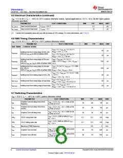
6.7 Switching Characteristics (continued)
VBB = 13.5 V, TJ = –40°C to +150°C (unless otherwise noted)
PARAMETER
TEST CONDITIONS
MIN
TYP
MAX
UNIT
1-ms enable pulse VBB = 13.5 V, RL
= 10 Ω
40
µs
–40
Turn-on and off matching
t
ON –tOFF
200-µs enable pulse, VBB = 13.5 V,
40
25
12
µs
%
%
RL = 10 Ω
–40
–25
–12
200-µs enable pulse (1-ms
period), VBB = 13.5 V, RL = 10 Ω
PWM accuracy - average load
current
ΔPWM
≤500 Hz, 50% Duty cycle VBB
13.5 V, RL = 10 Ω
=
Switching energy losses during turn-
on
EON
0.5
0.5
mJ
mJ
VBB = 13.5 V, RL = 10 Ω
VBB = 13.5 V, RL = 10 Ω
Switching energy losses during turn-
off
EOFF
Copyright © 2023 Texas Instruments Incorporated
Submit Document Feedback
9
Product Folder Links: TPS1HC30-Q1

 TI [ TEXAS INSTRUMENTS ]