TPS1HC30-Q1
ZHCSP75A –JULY 2022 –REVISED DECEMBER 2022
www.ti.com.cn
• Internal current limit: ILIM pin shorted to ground –If the external current limit is out of range on the lower end
or the ILIM pin is shorted to ground, the internal current limit is fixed and typically 12 A. To use the internal
current limit for large-current applications, tie the ILIM pin directly to the device GND.
• Internal current limit: ILIM pin open –If the external resistor is out of range on the higher end or the ILIM pin
is open, the current limit reverts to 6 A or half the current limit range. This level is still above the nominal
operation for the device to operate in DC STEADY state, but is low enough that if a pin fault occurs and the
RILIM opens up, the current does not default to the highest rating and put additional stress on the power
supply.
Both the internal current limit (Ilim,nom) and external programmable current limit are always active when VBB is
powered and EN is high. The lower value one (of ILIM and the external programmable current limit) is applied as
the actual current limit. The typical deglitch time for the current limit to assert is 2.5 µs.
Note that if a GND network is used (which leads to the level shift between the device GND and board GND), the
ILIM pin must be connected with device GND. Use Equation 2 to calculate RILIM
.
RILIM = KCL / ILIM
(2)
For better protection from a "hot short" condition (when VBB is high, channel is on, and a short to GND happens
suddenly), an overcurrent protection, OVCR, circuit is triggered that makes sure to limit the maximum current the
device allows to go through. With this OVCR, the device is protected during "hot short" events.
For more information about the current limiting feature, see the Short-Circuit and Overload Protection section.
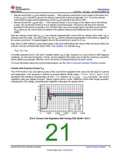
Current Limit Accuracy Across VDS
The TPS1HC30-Q1 has very tight accuracy of the current limit regulation level across the full range of currents
and temperature. This accuracy is defined at several defined RILIM values, 7.15 kΩ, 25 kΩ, and 71.5 kΩ
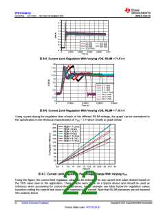
specified in the Electrical Characteristics at VDS = 3 V. However, as VDS (VBB – VOUT) increases , the current
regulation value also slightly increases. Taking a typical device, at the 3 different current limits ranges specified,
sweeping the VDS voltage, and plotting the regulation value gives the graphs below.
7
6.5
6
5.5
5
4.5
4
3.5
3
2.5
2
1.5
1
0.5
0
-0.5
-1
5 V VDS
6 V VDS
9 V VDS
13.5 V VDS
18 V VDS
24 V VDS
28 V VDS
0
0.0001
0.0002
0.0003
0.0004
0.0005
Time (s)
图8-4. Current Limit Regulation With Varying VDS, RILIM = 25 kΩ
Copyright © 2023 Texas Instruments Incorporated
Submit Document Feedback
21
Product Folder Links: TPS1HC30-Q1

 TI [ TEXAS INSTRUMENTS ]