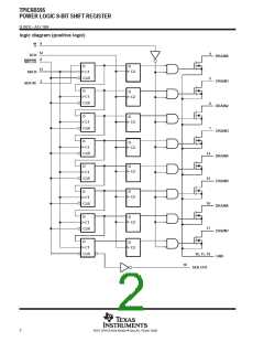
TPIC6B595
POWER LOGIC 8-BIT SHIFT REGISTER
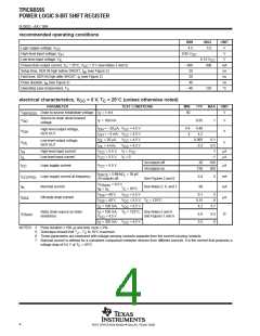
SLIS032 – JULY 1995
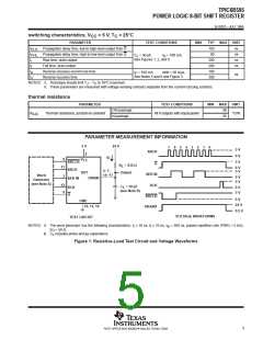
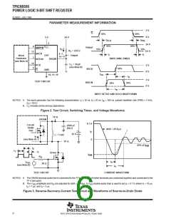
PARAMETER MEASUREMENT INFORMATION
5 V
0 V
G
50%
50%
5 V
24 V
t
t
PHL
PLH
2
24 V
90%
90%
8
V
CC
Output
SRCLR
SRCK
I
D
10%
10%
R
= 235 Ω
0.5 V
L
13
4–7,
14–17
t
t
f
r
DUT
Output
Word
Generator
(see Note A)
3
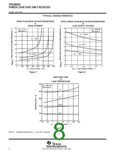
SWITCHING TIMES
DRAIN
SER IN
12
9
C
= 30 pF
L
RCK
G
5 V
0 V
(see Note B)
50%
SRCK
GND
t
10, 11, 19
TEST CIRCUIT
su
t
h
5 V
0 V
SER IN
50%
50%
t
w
INPUT SETUP AND HOLD WAVEFORMS
NOTES: A. The word generator has the following characteristics: t ≤ 10 ns, t ≤ 10 ns, t = 300 ns, pulsed repetition rate (PRR) = 5 kHz,
r
f
w
Z
C
= 50 Ω.
O
L
B.
includes probe and jig capacitance.
Figure 2. Test Circuit, Switching Times, and Voltage Waveforms
TP K
DRAIN
0.1 A
Circuit
Under
Test
2500 µF
250 V
di/dt = 20 A/µs
+
–
I
F
25 V
L = 1 mH
TP A
I
F
(see Note A)
0
25% of I
RM
t
2
t
1
t
3
Driver
I
RM
R
G
t
V
a
GG
(see Note B)
50 Ω
t
rr
TEST CIRCUIT
CURRENT WAVEFORM
NOTES: A. The DRAIN terminal under test is connected to the TP K test point. All other terminals are connected together and connected to the
TP A test point.
B. The V
amplitude and R are adjusted for di/dt = 20 A/µs. A V
double-pulse train is used to set I = 0.1 A, where t = 10 µs,
GG F 1
GG
= 7 µs, and t = 3 µs.
G
t
2
3
Figure 3. Reverse-Recovery-Current Test Circuit and Waveforms of Source-to-Drain Diode
6
POST OFFICE BOX 655303 • DALLAS, TEXAS 75265

 TI [ TEXAS INSTRUMENTS ]