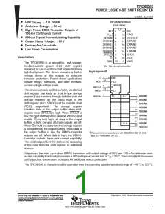
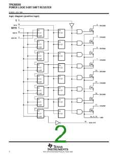
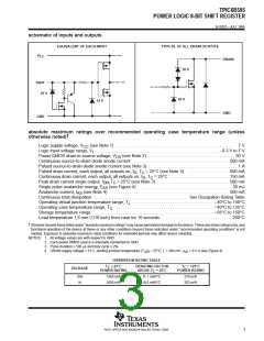
TPIC6B595
POWER LOGIC 8-BIT SHIFT REGISTER
SLIS032 – JULY 1995
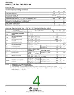
switching characteristics, V
= 5 V, T = 25°C
C
CC
PARAMETER
TEST CONDITIONS
MIN
TYP
150
90
MAX
UNIT
ns
t
t
t
t
t
t
Propagation delay time, low-to-high-level output from G
Propagation delay time, high-to-low-level output from G
Rise time, drain output
PLH
ns
PHL
C
= 30 pF,
See Figures 1, 2, and 9
I = 100 mA,
D
L
200
200
100
300
ns
r
Fall time, drain output
ns
f
Reverse-recovery-current rise time
Reverse-recovery time
a
rr
I
F
= 100 mA,
di/dt = 20 A/µs,
ns
See Notes 5 and 6 and Figure 3
NOTES: 5. Technique should limit T – T to 10°C maximum.
J
C
6. These parameters are measured with voltage-sensing contacts separate from the current-carrying contacts.
thermal resistance
PARAMETER
TEST CONDITIONS
MIN
MAX
90
UNIT
DW package
N package
R
Thermal resistance, junction-to-ambient
All 8 outputs with equal power
°C/W
θJA
95
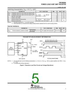
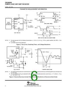
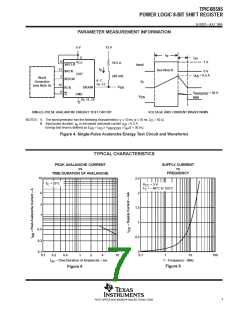
PARAMETER MEASUREMENT INFORMATION
5 V
24 V
7
6
5
4
3
2
1
0
5 V
SRCK
2
0 V
5 V
I
D
8
V
CC
SRCLR
SRCK
G
R
= 235 Ω
L
13
0 V
5 V
4–7,
14–17
DUT
Output
SER IN
Word
Generator
(see Note A)
3
0 V
5 V
DRAIN
SER IN
12
9
RCK
C
= 30 pF
RCK
G
L
0 V
5 V
(see Note B)
SRCLR
DRAIN1
0 V
GND
24 V
0.5 V
10, 11, 19
VOLTAGE WAVEFORMS
TEST CIRCUIT
NOTES: A. The word generator has the following characteristics: t ≤ 10 ns, t ≤ 10 ns, t = 300 ns, pulsed repetition rate (PRR) = 5 kHz,
r
f
w
Z
C
= 50 Ω.
O
L
B.
includes probe and jig capacitance.
Figure 1. Resistive-Load Test Circuit and Voltage Waveforms
5
POST OFFICE BOX 655303 • DALLAS, TEXAS 75265

 TI [ TEXAS INSTRUMENTS ]