TMS3705
11-07-22-003 – SCBS881B –JANUARY 2010–REVISED APRIL 2010
www.ti.com
ELECTRICAL CHARACTERISTICS (continued)
VDD = 4.5 V to 5.5 V, fosc = 4 MHz, F_SEL = high, over operating free-air temperature range (unless otherwise noted)
PARAMETER
TEST CONDITIONS
MIN
TYP
MAX UNIT
Diagnosis (SENSE)
Current threshold for operating
antenna(4)
Idiag
80
240
µA
Phase-Locked Loop (D_TST)
fpll
PLL frequency
15.984
16
16.0166 MHz
Δf/fpll
Jitter of the PLL frequency
6
%
Power-On Reset (POR)
Vpor_r
Vpor_f
POR threshold voltage, rising
POR threshold voltage, falling
VDD rising with low slope
VDD falling with low slope
1.9
1.3
3.5
2.6
V
V
(4) Internal resistance switched on and much lower than external SENSE resistance.
SWITCHING CHARACTERISTICS
VDD = 4.5 V to 5.5 V, fosc = 4 MHz, F_SEL = high, over operating free-air temperature range (unless otherwise noted)
PARAMETER
TEST CONDITIONS
MIN
TYP
MAX UNIT
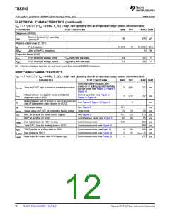
From start of the oscillator after
power-on or waking up until reaching
the idle mode (see Figure 2, Figure 3,
Figure 4)
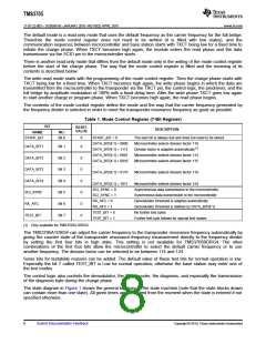
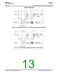
tinit min Time for TXCT high to initialize a new transmission
2
2.05
2.2
2.2
ms
Delay between leaving idle mode and start of
diagnosis byte at SCIO
Normal operation (see Figure 2,
Figure 3, Figure 4)
tdiag
2
2.12
3
ms
ms
Delay between end of charge or end of program and
start of transponder data transmit on SCIO
tR
See Figure 2, Figure 3, Figure 4)
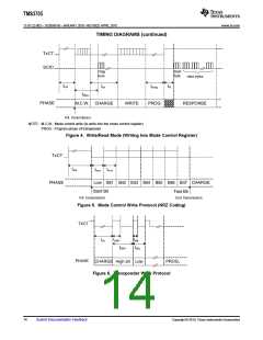
toff
Write pulse pause
See Figure 6
0.1
73
ms
µs
µs
µs
µs
µs
µs
µs
µs
tdwrite
tmcr
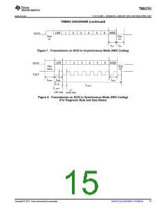
tsci
Signal delay on TXCT for controlling the full bridge
NRZ bit duration for mode control register
NRZ bit duration on SCIO
Write mode
79
128
64
85
135
See Figure 5
121
63
Asynchronous mode (see Figure 7)
Synchronous mode
65
tdstop
Low signal delay on TXCT to stop
128
800
tt_sync Total TXCT time for reading data on SCIO
tsync TXCT period for shifting data on SCIO
tL_sync Low phase on TXCT
tready Data ready for output after SCIO goes high
Synchronous mode (see Figure 8)
Synchronous mode (seeFigure 8)
Synchronous mode (see Figure 8)
Synchronous mode (see Figure 8)
900
4
2
1
64
32
100
tsync – 2
127
12
Submit Documentation Feedback
Copyright © 2010, Texas Instruments Incorporated

 TI [ TEXAS INSTRUMENTS ]