ꢀ ꢁ ꢂ ꢃ ꢄꢅ ꢆ ꢇ ꢄꢈꢈ ꢉ ꢀꢁ ꢂꢃ ꢄ ꢅ ꢆꢇ ꢄ ꢈꢈ ꢊ
ꢋ ꢌ ꢍꢎꢏ ꢐꢑ ꢒꢌ ꢓ ꢀ ꢏ ꢌ ꢔꢌ ꢀꢕꢖ ꢂ ꢌ ꢔꢓ ꢕꢖ ꢑ ꢗꢒ ꢆꢎꢂ ꢂꢒ ꢗꢂ
SPRS073L − AUGUST 1998 − REVISED JUNE 2005
IEEE 1149.1 JTAG compatibility statement
The TMS320C6211/C6211B DSP requires that both TRST and RESET resets be asserted upon power up to
be properly initialized. While RESET initializes the DSP core, TRST initializes the DSP’s emulation logic. Both
resets are required for proper operation.
While both TRST and RESET need to be asserted upon power up, only RESET needs to be released for the
DSP to boot properly. TRST may be asserted indefinitely for normal operation, keeping the JTAG port interface
and DSP’s emulation logic in the reset state.
TRST only needs to be released when it is necessary to use a JTAG controller to debug the DSP or exercise
the DSP’s boundary scan functionality.
For maximum reliability, the TMS320C6211/C6211B DSP includes an internal pulldown (IPD) on the TRST pin
to ensure that TRST will always be asserted upon power up and the DSP’s internal emulation logic will always
be properly initialized.
JTAG controllers from Texas Instruments actively drive TRST high. However, some third-party JTAG controllers
may not drive TRST high but expect the use of an external pullup resistor on TRST.
When using this type of JTAG controller, assert TRST to initialize the DSP after powerup and externally drive
TRST high before attempting any emulation or boundary scan operations. Following the release of RESET, the
low-to-high transition of TRST must be “seen” to latch the state of EMU1 and EMU0. The EMU[1:0] pins
configure the device for either Boundary Scan mode or Emulation mode. For more detailed information, see
the terminal functions section of this data sheet.
EMIF device speed
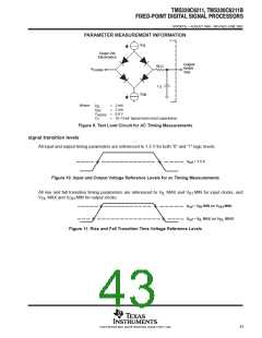
TI recommends utilizing the input/output buffer information specification (IBIS) models to analyze all AC timings.
To properly use IBIS models to attain accurate timing analysis for a given system, see the Using IBIS Models
for Timing Analysis application report (literature number SPRA839).
40
POST OFFICE BOX 1443 • HOUSTON, TEXAS 77251−1443

 TI [ TEXAS INSTRUMENTS ]