TMS320F28027, TMS320F28027-Q1, TMS320F28027F, TMS320F28027F-Q1, TMS320F28026
TMS320F28026-Q1, TMS320F28026F, TMS320F28026F-Q1, TMS320F28023
TMS320F28023-Q1, TMS320F28022, TMS320F28021, TMS320F28020, TMS320F280200
ZHCSA13P –NOVEMBER 2008 –REVISED FEBRUARY 2021
www.ti.com.cn
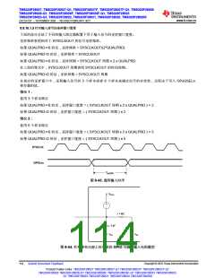
9.9.10.1.4 低功耗唤醒时序
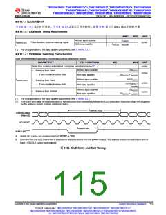
节9.9.10.1.4.1 显示时序要求,节9.9.10.1.4.2 显示了开关特性,而图9-45 显示了IDEL 模式下的时序图
9.9.10.1.4.1 IDLE Mode Timing Requirements
MIN(1)
2tc(SCO)
MAX
UNIT
Without input qualifier
With input qualifier
tw(WAKE-INT)
Pulse duration, external wake-up signal
cycles
5tc(SCO) + tw(IQSW)
(1) For an explanation of the input qualifier parameters, see 节9.9.10.1.2.1.
9.9.10.1.4.2 IDLE Mode Switching Characteristics
over recommended operating conditions (unless otherwise noted)
PARAMETER(1)
TEST CONDITIONS
MIN
MAX
UNIT
Delay time, external wake signal to program execution resume (2)
cycles
Without input qualifier
With input qualifier
Without input qualifier
With input qualifier
20tc(SCO)
•
Wake up from Flash
cycles
– Flash module in active state
20tc(SCO) + tw(IQSW)
1050tc(SCO)
1050tc(SCO)
tw(IQSW)
20tc(SCO)
td(WAKE-IDLE)
•
Wake up from Flash
cycles
cycles
+
– Flash module in sleep state
Without input qualifier
With input qualifier
•
Wake up from SARAM
20tc(SCO) + tw(IQSW)
(1) For an explanation of the input qualifier parameters, see 节9.9.10.1.2.1.
(2) This is the time taken to begin execution of the instruction that immediately follows the IDLE instruction. Execution of an ISR (triggered
by the wake-up signal) involves additional latency.
t
d(WAKE−IDLE)
Address/Data
(internal)
XCLKOUT
t
w(WAKE−INT)
WAKE INT(A)(B)
A. WAKE INT can be any enabled interrupt, WDINT or XRS.
B. From the time the IDLE instruction is executed to place the device into low-power mode (LPM), wakeup should not be initiated until at
least 4 OSCCLK cycles have elapsed.
图9-45. IDLE Entry and Exit Timing
Copyright © 2022 Texas Instruments Incorporated
Submit Document Feedback
115
Product Folder Links: TMS320F28027 TMS320F28027-Q1 TMS320F28027F TMS320F28027F-Q1
TMS320F28026 TMS320F28026-Q1 TMS320F28026F TMS320F28026F-Q1 TMS320F28023 TMS320F28023-
Q1 TMS320F28022 TMS320F28021 TMS320F28020 TMS320F280200

 TI [ TEXAS INSTRUMENTS ]