TMS320C6678
Multicore Fixed and Floating-Point Digital Signal Processor
SPRS691D—April 2013
www.ti.com
Changed 2 to OUTPUT_DIVIDE in the clock formula in PLL Boot Configuration Settings section (Page 41)
Changed EMAC to GbE switch subsystem (Page 223)
Changed EMAC to Gigabit Ethernet (GbE) Switch Subsystem (Page 225)
Changed EMAC to Gigabit Ethernet Switch (Page 73)
Changed EMAC to Network Coprocessor Packet DMA (Page 98)
Changed Ethernet MAC Subsystem to Gigabit Ethernet Switch Subsystem in Features (Page 13)
Changed PA_SS into Network Coprocessor Packet DMA in Device Master Settings table (Page 190)
Changed PA_SS into PASS in the Clock Sequencing table (Page 126)
Changed Packet Accelerator into Network Coprocessor and corrected the memory address in the memory map summary table (Page 21)
Changed Packet Accelerator into network coprocessor in Security Accelerator section (Page 222)
Changed Packet Accelerator into Network Coprocessor in the Device Configuration Pins table. (Page 74)
Changed Packet Accelerator subsystem into Network Coprocessor (Page 154)
Changed Packet Subsystem to Network Coprocessor (PASS PLL) in Terminal Functions table (Page 47)
Changed PASS into Network Coprocessor (PASS) (Page 140)
Changed PS_SS_CLK PLL to PASS_CLK PLL in Terminal Functions table (Page 47)
Deleted section 5.5 "C66x CorePac Resets" to avoid confusion and the reset details are covered in "Reset Controller" section (Page 108)
Removed EMAC in Characteristics of the device Processor table (Page 17)
Added BGA Package row into Characteristics of Processor table (Page 17)
Corrected End and Bytes of DDR3 EMIF Configuration section in Memory Map Summary table (Page 21)
Corrected BAR number from BAR1/2 to BAR2/3 and BAR3/4 to BAR4/5 in PCIe Window Sizes table (Page 32)
Deleted EDMA3 Peripheral Register Description section, which is covered in EDMA user guide (Page 156)
Added SERDES PLL Status and Config registers (Page 75)
Added "to DDR3 memory space" to the first step of workaround (Page 203)
Added "with TCCMOD=0" after "e.g. EDMA3 transfer controllers" (Page 203)
Added CPTS_RFTCLK_SEL register in GbE Switch Subsystem section (Page 223)
Changed "DSP/2" to "CPU/2" and "DSP/3" to "CPU/3" (Page 98)
Changed the word "can" to "must" in the sentence "for most applications increment mode can be used" to specify it is a hard rule.
(Page 157)
Corrected the tw(RXSTOP15) and tw(RXSTOP2) values in UART Timing Requirements table (Page 216)
Changed "sleep boot" to "No boot" in Sub-Mode field of No boot/EMIF16 Configuration Bit Field Descriptions table (Page 30)
Changed Section 2.5.2.1 title from "Sleep/EMIF16" to "No Boot/EMIF16" (Page 30)
Corrections Applied to I2C Passive Mode Device Configuration Bit Fields (Page 33)
Corrections Applied to I2C Passive Mode Device Configuration Field Descriptions (Page 33)
Modified description of value 0 to EMIF16/No Boot in Boot Device Values table (Page 29)
Corrected SRIO configuration memory map from 0x02900000~0x02907FFF to 0x02900000~0x02920FFF (Page 21)
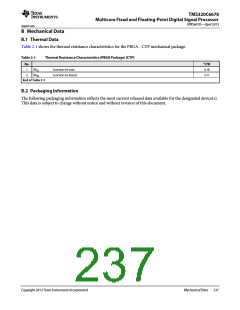
Added thermal values into the Thermal Resistance Characteristics table. (Page 237)
Added DDR3PLLCTL1 register and field description table (Page 152)
Added more description to pin PTV15 in the Terminal Functions table (Page 48)
Added PASSPLLCTL1 register and field descriptions (Page 155)
Added Master ID Settings table. (Page 191)
Added the table of Power Supply to Peripheral I/O Mapping (Page 119)
Changed PROGn_MPEAR register table format and reset value format (Page 198)
Changed PROGn_MPSAR registers table format and reset value format (Page 198)
Modified the figure of SmartReflex 4-Pin VID Interface Timing (Page 127)
Modified the table of SmartReflex 4-Pin VID Interface Switching Characteristics (Page 127)
Added PROG4 registers set into MPU1 Registers table (Page 194)
Changed number of programmable ranges supported from 4 to 5 for MPU1 (Page 190)
Modified reset values in MPU Configuration Register table (Page 197)
Modified Table 2-13 to include 1000 MHz and 1250 MHz columns. (Page 41)
Added BWADJ[11:8] to MAINPLLCTL1 register table and description. (Page 149)
Changed Privilege ID from the second column to the first column (Page 190)
Changed PROG3_MPEA to PROG3_MPEAR in MPU1 Registers table (Page 194)
Changed Programmable range enumeration from 1-N based to 0-N based in MPU Register Map. (Page 193)
Changed SRIO_CPPI and SRIO_M rows to the single row (Page 190)
Copyright 2013 Texas Instruments Incorporated
Revision History 235

 TI [ TEXAS INSTRUMENTS ]