TMS320C6678
Multicore Fixed and Floating-Point Digital Signal Processor
SPRS691D—April 2013
www.ti.com
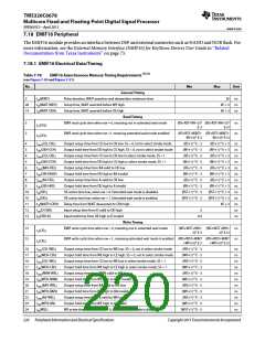
Table 7-78
EMIF16 Asynchronous Memory Timing Requirements (1) (2)
(see Figure 7-50 and Figure 7-51)
No.
Min
Max
Unit
ns
24
26
27
25
tw(WEL)
WE active time low, when ew = 1. Extended wait mode is enabled.
Output setup time from D valid to WE low
(WST+1) * E - 3
(WS+1) * E - 3
(WH+1) * E - 3
tosu(DV-WEL)
toh(WEH-DIV)
ns
Output hold time from WE high to D invalid
ns
td(WAITH-WEH) Delay time from WAIT deasserted to WE# high
4E + 3
ns
End of Table 7-78
1 E = 1/SYSCLK7, RS = Read Setup, RST = Read Strobe, RH = Read Hold, WS = Write Setup, WST = Write Strobe, WH = Write Hold.
2 WAIT = number of cycles wait is asserted between the programmed end of the strobe period and wait de-assertion.
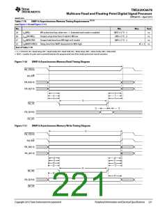
Figure 7-50
EMIF16 Asynchronous Memory Read Timing Diagram
3
EM_CE[3:0]
EM_R/W
EM_BA[1:0]
EM_A[21:0]
4
9
7
6
8
5
10
EM_OE
12
13
EM_D[15:0]
EM_WE
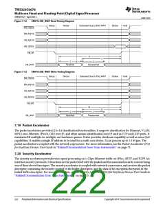
Figure 7-51
EMIF16 Asynchronous Memory Write Timing Diagram
15
EM_CE[3:0]
EM_R/W
EM_BA[1:0]
EM_A[21:0]
16
18
20
22
19
21
23
17
24
EM_WE
26
27
EM_D[15:0]
EM_OE
Copyright 2013 Texas Instruments Incorporated
Peripheral Information and Electrical Specifications 221

 TI [ TEXAS INSTRUMENTS ]