TMS320C6678
Multicore Fixed and Floating-Point Digital Signal Processor
SPRS691D—April 2013
www.ti.com
7.18 EMIF16 Peripheral
The EMIF16 module provides an interface between DSP and external memories such as NAND and NOR flash. For
more information, see the External Memory Interface (EMIF16) for KeyStone Devices User Guide in ‘‘Related
Documentation from Texas Instruments’’ on page 73.
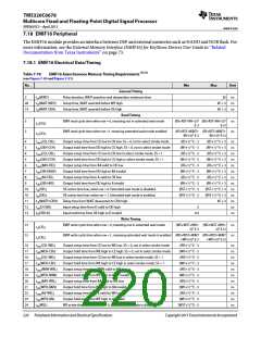
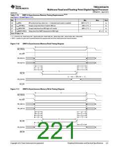
7.18.1 EMIF16 Electrical Data/Timing
Table 7-78
EMIF16 Asynchronous Memory Timing Requirements (1) (2)
(see Figure 7-50 and Figure 7-51)
No.
Min
Max
Unit
General Timing
2
tw(WAIT)
Pulse duration, WAIT assertion and deassertion minimum time
Setup time, WAIT asserted before WE high
Setup time, WAIT asserted before OE high
2E ns
28
14
td(WAIT-WEH)
td(WAIT-OEH)
4E + 3
4E + 3
ns
ns
Read Timing
3
3
EMIF read cycle time when ew = 0, meaning not in extended wait mode
(RS+RST+RH+3)* (RS+RST+RH+3)* ns
E-3 E+3
tC(CEL)
tC(CEL)
EMIF read cycle time when ew =1, meaning extended wait mode enabled
(RS+RST+WAIT+ (RS+RST+WAIT+
ns
RH+3)* E-3
(RS+1) * E - 3
(RH+1) * E - 3
(RS+1) * E - 3
(RH+1) * E - 3
(RS+1) * E - 3
(RH+1) * E - 3
(RS+1) * E - 3
(RH+1) * E - 3
(RST+1) * E - 3
(RST+1) * E - 3
RH+3)* E+3
(RS+1) * E + 3
(RH+1) * E + 3
(RS+1) * E + 3
(RH+1) * E + 3
(RS+1) * E + 3
(RH+1) * E + 3
(RS+1) * E + 3
(RH+1) * E + 3
(RST+1) * E + 3
(RST+1) * E + 3
4E + 3
4
t
osu(CEL-OEL)
Output setup time from CE low to OE low. SS = 0, not in select strobe mode
Output hold time from OE high to CE high. SS = 0, not in select strobe mode
Output setup time from CE low to OE low in select strobe mode, SS = 1
Output hold time from OE high to CE high in select strobe mode, SS = 1
Output setup time from BA valid to OE low
ns
ns
ns
ns
ns
ns
ns
ns
ns
ns
ns
ns
ns
5
toh(OEH-CEH)
tosu(CEL-OEL)
toh(OEH-CEH)
tosu(BAV-OEL)
toh(OEH-BAIV)
tosu(AV-OEL)
toh(OEH-AIV)
tw(OEL)
4
5
6
7
Output hold time from OE high to BA invalid
8
Output setup time from A valid to OE low
9
Output hold time from OE high to A invalid
10
10
11
12
13
OE active time low, when ew = 0. Extended wait mode is disabled.
OE active time low, when ew = 1. Extended wait mode is enabled.
Delay time from WAIT deasserted to OE# high
tw(OEL)
td(WAITH-OEH)
tsu(D-OEH)
Input setup time from D valid to OE high
3
th(OEH-D)
Input hold time from OE high to D invalid
0.5
Write Timing
15
15
EMIF write cycle time when ew = 0, meaning not in extended wait mode
(WS+WST+WH+ (WS+WST+WH+
3)* E-3 3)* E+3
ns
ns
tc(CEL)
tc(CEL)
EMIF write cycle time when ew =1., meaning extended wait mode is enabled (WS+WST+WAIT (WS+WST+WAIT
+WH+3)* E-3
(WS+1) * E - 3
(WH+1) * E - 3
(WS+1) * E - 3
(WH+1) * E - 3
(WS+1) * E - 3
(WH+1) * E - 3
(WS+1) * E - 3
(WH+1) * E - 3
(WS+1) * E - 3
(WH+1) * E - 3
(WST+1) * E - 3
+WH+3)* E+3
16
17
16
17
18
19
20
21
22
23
24
t
osu(CEL-WEL)
Output setup time from CE low to WE low. SS = 0, not in select strobe mode
Output hold time from WE high to CE high. SS = 0, not in select strobe mode
Output setup time from CE low to WE low in select strobe mode, SS = 1
Output hold time from WE high to CE high in select strobe mode, SS = 1
Output setup time from RNW valid to WE low
ns
ns
ns
ns
ns
ns
ns
ns
ns
ns
ns
toh(WEH-CEH)
tosu(CEL-WEL)
toh(WEH-CEH)
tosu(RNW-WEL)
toh(WEH-RNW)
tosu(BAV-WEL)
toh(WEH-BAIV)
tosu(AV-WEL)
toh(WEH-AIV)
tw(WEL)
Output hold time from WE high to RNW invalid
Output setup time from BA valid to WE low
Output hold time from WE high to BA invalid
Output setup time from A valid to WE low
Output hold time from WE high to A invalid
WE active time low, when ew = 0. Extended wait mode is disabled.
220
Peripheral Information and Electrical Specifications
Copyright 2013 Texas Instruments Incorporated

 TI [ TEXAS INSTRUMENTS ]