TMS320C6678
Multicore Fixed and Floating-Point Digital Signal Processor
SPRS691D—April 2013
www.ti.com
7.15 UART Peripheral
The universal asynchronous receiver/transmitter (UART) module provides an interface between the DSP and
UART terminal interface or other UART-based peripheral. The UART is based on the industry standard TL16C550
asynchronous communications element, which in turn is a functional upgrade of the TL16C450. Functionally
similar to the TL16C450 on power up (single character or TL16C450 mode), the UART can be placed in an alternate
FIFO (TL16C550) mode. This relieves the DSP of excessive software overhead by buffering received and transmitted
characters. The receiver and transmitter FIFOs store up to 16 bytes including three additional bits of error status per
byte for the receiver FIFO.
The UART performs serial-to-parallel conversions on data received from a peripheral device and parallel-to-serial
conversion on data received from the DSP. The DSP can read the UART status at any time. The UART includes
control capability and a processor interrupt system that can be tailored to minimize software management of the
communications link. For more information on UART, see the Universal Asynchronous Receiver/Transmitter
(UART) for KeyStone Devices User Guide in ‘‘Related Documentation from Texas Instruments’’ on page 73.
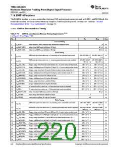
Table 7-74
UART Timing Requirements
(see Figure 7-44 and Figure 7-45)
No.
Min
Max
Unit
Receive Timing
4
5
5
6
6
6
tw(RXSTART)
tw(RXH)
Pulse width, receive start bit
0.96U (1)
0.96U
1.05U
ns
ns
ns
ns
ns
ns
Pulse width, receive data/parity bit high
Pulse width, receive data/parity bit low
Pulse width, receive stop bit 1
1.05U
1.05U
1.05U
tw(RXL)
0.96U
tw(RXSTOP1)
tw(RXSTOP15)
tw(RXSTOP2)
0.96U
Pulse width, receive stop bit 1.5
Pulse width, receive stop bit 2
1.5*(0.96U) 1.5*(1.05U)
2*(0.96U)
2*(1.05U)
Autoflow Timing Requirements
Delay time, CTS asserted to START bit transmit
8
td(CTSL-TX)
P (2)
5P
ns
End of Table 7-74
1 U = UART baud time = 1/programmed baud rate
2 P = 1/SYSCLK7
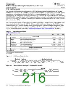
Figure 7-44
UART Receive Timing Waveform
5
5
6
4
RXD
Start
Bit 0
Bit 1
Bit N-1
Bit N
Parity
Stop
Idle
Start
Stop/Idle
Figure 7-45
UART CTS (Clear-to-Send Input) — Autoflow Timing Waveform
8
TXD
CTS
Bit N-1
Bit N
Stop
Start
Bit 0
216
Peripheral Information and Electrical Specifications
Copyright 2013 Texas Instruments Incorporated

 TI [ TEXAS INSTRUMENTS ]