TMS320C6672
Multicore Fixed and Floating-Point Digital Signal Processor
SPRS708C—February 2012
www.ti.com
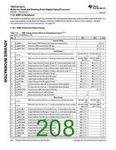
Table 7-72
UART Switching Characteristics
(See Figure 7-45 and Figure 7-46)
No.
Parameter
Min
U (1) - 2
Max
Unit
Transmit Timing
1
2
2
3
3
3
tw(TXSTART)
tw(TXH)
Pulse width, transmit start bit
U + 2
ns
ns
ns
ns
ns
ns
Pulse width, transmit data/parity bit high
Pulse width, transmit data/parity bit low
Pulse width, transmit stop bit 1
U - 2
U - 2
U - 2
U + 2
U + 2
U + 2
tw(TXL)
tw(TXSTOP1)
tw(TXSTOP15)
tw(TXSTOP2)
Pulse width, transmit stop bit 1.5
Pulse width, transmit stop bit 2
1.5 * (U - 2) 1.5 * ('U + 2)
2 * (U - 2)
2 * ('U + 2)
Autoflow Timing Requirements
Delay time, STOP bit received to RTS deasserted
7
td(RX-RTSH)
P (2)
5P
ns
End of Table 7-72
1 U = UART baud time = 1/programmed baud rate
2 P = 1/SYSCLK7
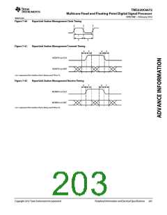
Figure 7-45
UART Transmit Timing Waveform
2
2
3
1
TXD
Start
Bit 0
Bit 1
Bit N-1
Bit N
Parity
Stop
Idle
Start
Stop/Idle
Figure 7-46
UART RTS (Request-to-Send Output) — Autoflow Timing Waveform
7
RXD
CTS
Bit N-1
Bit N
Stop
Start
7.16 PCIe Peripheral
The two-lane PCI express (PCIe) module on the device provides an interface between the DSP and other
PCIe-compliant devices. The PCI Express module provides low-pin-count, high-reliability, and high-speed data
transfer at rates of 5.0 GBaud per lane on the serial links. For more information, see the Peripheral Component
Interconnect Express (PCIe) for KeyStone Devices User Guide in ‘‘Related Documentation from Texas Instruments’’
on page 69. The PCIe electrical requirements are fully specified in the PCI Express Base Specification Revision 2.0
of PCI-SIG. TI has performed the simulation and system characterization to ensure all PCIe interface timings in this
solution are met; therefore, no electrical data/timing information is supplied here for this interface.
Copyright 2012 Texas Instruments Incorporated
Peripheral Information and Electrical Specifications 205

 TI [ TEXAS INSTRUMENTS ]