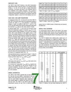
ONE-SHOT (OS)
Byte
D7
D6
D5
D4
D3
D2
D1
D0
1
H11
H10
H9
H8
H7
H6
H5
H4
The TMP175 and TMP75 feature a One-Shot Temperature
Measurement Mode. When the device is in Shutdown Mode,
writing a 1 to the OS bit will start a single temperature
conversion. The device will return to the shutdown state at
the completion of the single conversion. This is useful to
reduce power consumption in the TMP175 and TMP75 when
continuous temperature monitoring is not required. When the
configuration register is read, the OS will always read zero.
Byte
D7
D6
D5
D4
D3
D2
D1
D0
2
H3
H2
H1
H0
0
0
0
0
TABLE IX. Bytes 1 and 2 of THIGH Register.
Byte
D7
D6
D5
D4
D3
D2
D1
D0
1
L11
L10
L9
L8
L7
L6
L5
L4
Byte
D7
D6
D5
D4
D3
D2
D1
D0
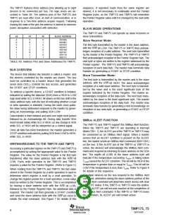
HIGH AND LOW LIMIT REGISTERS
2
L3
L2
L1
L0
0
0
0
0
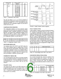
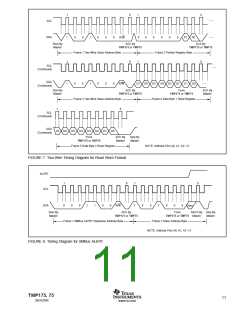
In Comparator Mode (TM = 0), the ALERT pin of the TMP175
and TMP75 becomes active when the temperature equals or
exceeds the value in THIGH and generates a consecutive
number of faults according to fault bits F1 and F0. The
ALERT pin will remain active until the temperature falls below
the indicated TLOW value for the same number of faults.
TABLE X. Bytes 1 and 2 of TLOW Register.
speed (1kHz to 3.4MHz) modes. All data bytes are transmit-
ted MSB first.
In Interrupt Mode (TM = 1), the ALERT pin becomes active
when the temperature equals or exceeds THIGH for a con-
secutive number of fault conditions. The ALERT pin remains
active until a read operation of any register occurs, or the
device successfully responds to the SMBus Alert Response
Address. The ALERT pin will also be cleared if the device is
placed in Shutdown Mode. Once the ALERT pin is cleared,
it will only become active again by the temperature falling
below TLOW. When the temperature falls below TLOW, the
ALERT pin will become active and remain active until cleared
by a read operation of any register or a successful response
to the SMBus Alert Response Address. Once the ALERT pin
is cleared, the above cycle will repeat, with the ALERT pin
becoming active when the temperature equals or exceeds
SERIAL BUS ADDRESS
To communicate with the TMP175 and TMP75, the master
must first address slave devices via a slave address byte.
The slave address byte consists of seven address bits, and
a direction bit indicating the intent of executing a read or write
operation.
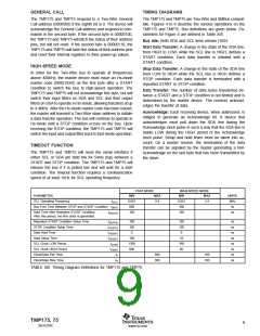
The TMP175 features three address pins to allow up to 27
devices to be addressed on a single bus interface. Table XI
describes the pin logic levels used to properly connect up to 27
devices. ‘1’ indicates the pin is connected to the supply (VCC);
‘0’ indicates the pin is connected to GND; Float indicates the
pin is left unconnected. The state of pins A0, A1, and A2 is
sampled on every bus communication and should be set prior
to any activity on the interface.
T
HIGH. The ALERT pin can also be cleared by resetting the
device with the General Call Reset command. This will also
clear the state of the internal registers in the device returning
the device to Comparator Mode (TM = 0).
A2
A1
A0
SLAVE ADDRESS
0
0
0
0
1
1
1
0
0
1
1
0
0
1
1
0
0
0
1
1
0
1
0
1
0
1
0
1
0
Float
1
0
Float
1
0
1
0
1
0
1001000
1001001
1001010
1001011
1001100
1001101
1001110
1001111
1110000
1110001
1110010
1110011
1110100
1110101
1110110
1110111
0101000
0101001
0101010
0101011
0101100
0101101
0101110
0101111
0110101
0110110
0110111
Both operational modes are represented in Figure 3. Tables IX
and X describe the format for the THIGH and TLOW registers.
Power-up Reset values for THIGH and TLOW are:
THIGH = 80°C and TLOW = 75°C.
The format of the data for THIGH and TLOW is the same as for
the Temperature Register.
1
Float
Float
Float
Float
Float
Float
Float
Float
0
0
1
1
0
All 12 bits for the Temperature, THIGH, and TLOW registers are
used in the comparisons for the ALERT function for all
converter resolutions. The three LSBs in THIGH and TLOW can
affect the ALERT output even if the converter is configured
for 9-bit resolution.
1
Float
Float
Float
Float
Float
Float
0
1
0
1
SERIAL INTERFACE
1
The TMP175 and TMP75 operate only as slave devices on
the Two-Wire bus and SMBus. Connections to the bus are
made via the open-drain I/O lines SDA and SCL. The SDA
and SCL pins feature integrated spike suppression filters
and Schmitt triggers to minimize the effects of input spikes
and bus noise. The TMP175 and TMP75 both support the
transmission protocol for fast (1kHz to 400kHz) and high-
Float
Float
Float
Float
Float
Float
Float
0
1
1
0
Float
Float
Float
1
Float
TABLE XI. Address Pins and Slave Addresses for TMP175.
TMP175, 75
7
SBOS288C
www.ti.com

 TI [ TEXAS INSTRUMENTS ]