APPLICATIONS INFORMATION
The TMP175 and TMP75 are digital temperature sensors
that are optimal for thermal management and thermal protec-
tion applications. The TMP175 and TMP75 are Two-Wire
and SMBus interface-compatible, and are specified over a
temperature range of –40°C to +125°C.
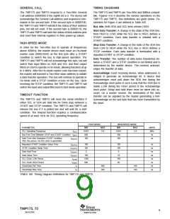
Pointer
Register
Temperature
Register
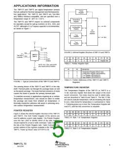
The TMP175 and TMP75 require no external components
for operation except for pull-up resistors on SCL, SDA, and
ALERT, although a 0.1µF bypass capacitor is recommended,
as shown in Figure 1.
SCL
SDA
Configuration
Register
I/O
Control
Interface
TLOW
Register
THIGH
V+
Register
0.1µF
8
7
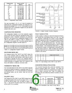
FIGURE 2. Internal Register Structure of TMP175 and TMP75.
A0
A1
A2
SCL
SDA
2
1
To
Two-Wire
Controller
6
5
3
TMP175
TMP75
P7
P6
P5
P4
P3
P2
P1
P0
ALERT
0
0
0
0
0
0
Register Bits
(Output)
4
TABLE I. Pointer Register Byte.
NOTE: SCL, SDA, and ALERT
pins require pull-up resistors.
P1
P0
REGISTER
GND
0
0
1
1
0
1
0
1
Temperature Register (READ Only)
Configuration Register (READ/WRITE)
TLOW Register (READ/WRITE)
THIGH Register (READ/WRITE)
TABLE II. Pointer Addresses of the TMP175 and TMP75
Registers.
FIGURE 1. Typical Connections of the TMP175 and TMP75.
The sensing device of the TMP175 and TMP75 is the chip
itself. Thermal paths run through the package leads as well
as the plastic package. The lower thermal resistance of metal
causes the leads to provide the primary thermal path.
TEMPERATURE REGISTER
The Temperature Register of the TMP175 or TMP75 is a
12-bit, read-only register that stores the output of the most
recent conversion. Two bytes must be read to obtain data,
and are described in Table III and Table IV. The first 12 bits
are used to indicate temperature, with all remaining bits equal
to zero. Data format for temperature is summarized in Table
V. Following power-up or reset, the Temperature Register will
read 0°C until the first conversion is complete.
To maintain accuracy in applications requiring air or surface
temperature measurement, care should be taken to isolate
the package and leads from ambient air temperature. A
thermally-conductive adhesive will assist in achieving accu-
rate surface temperature measurement.
POINTER REGISTER
D7
D6
D5
D4
D3
D2
D1
D0
Figure 2 shows the internal register structure of the TMP175
and TMP75. The 8-bit Pointer Register of the devices are
used to address a given data register. The Pointer Register
uses the two LSBs to identify which of the data registers
should respond to a read or write command. Table I identifies
the bits of the Pointer Register byte. Table II describes the
pointer address of the registers available in the TMP175 and
TMP75. Power-up Reset value of P1/P0 is 00.
T11
T10
T9
T8
T7
T6
T5
T4
TABLE III. Byte 1 of Temperature Register.
D7
D6
D5
D4
D3
D2
D1
D0
T3
T2
T1
T0
0
0
0
0
TABLE IV. Byte 2 of Temperature Register.
TMP175, 75
5
SBOS288C
www.ti.com

 TI [ TEXAS INSTRUMENTS ]