TMP451
SBOS686 –JUNE 2013
www.ti.com
TIMEOUT FUNCTION
The TMP451 resets the serial interface if either SCL or SDA are held low for 25 ms (typical) between a start and
stop condition. If the TMP451 is holding the bus low, the device releases the bus and waits for a start condition.
To avoid activating the timeout function, it is necessary to maintain a communication speed of at least 1 kHz for
the SCL operating frequency.
SHUTDOWN MODE (SD)
The TMP451 shutdown mode enables the user to save maximum power by shutting down all device circuitry
other than the serial interface, reducing current consumption to typically less than 3 μA; see Figure 10, Shutdown
Quiescent Current vs Supply Voltage. Shutdown mode is enabled when SD (bit 6) of configuration register is
high; the device shuts down after the current conversion is finished. When SD is low, the device maintains a
continuous-conversion state.
SENSOR FAULT
The TMP451 can sense a fault at the D+ input resulting from incorrect diode connection. The TMP451 can also
sense an open circuit. Short-circuit conditions return a value of –64°C. The detection circuitry consists of a
voltage comparator that trips when the voltage at D+ exceeds (V+) – 0.3 V (typical). The comparator output is
continuously checked during a conversion. If a fault is detected, then OPEN (bit 2) in the status register is set to
'1'.
When not using the remote sensor with the TMP451, the D+ and D– inputs must be connected together to
prevent meaningless fault warnings.
FILTERING
Remote junction temperature sensors are usually implemented in a noisy environment. Noise is most often
created by fast digital signals, and it can corrupt measurements. The TMP451 has a built-in, 65-kHz filter on the
inputs of D+ and D– to minimize the effects of noise. However, a bypass capacitor placed differentially across the
inputs of the remote temperature sensor is recommended to make the application more robust against unwanted
coupled signals. For this capacitor, choose a value of between 100 pF and 1 nF. Some applications attain better
overall accuracy with additional series resistance; however, this increased accuracy is application-specific. When
series resistance is added, the total value should not be greater than 1 kΩ. If filtering is required, suggested
component values are 100 pF and 50 Ω on each input; exact values are application-specific.
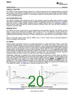
Additionally, a digital filter is available for the remote temperature measurements to further reduce the effect of
noise. This filter is programmable and has two levels when enabled. Level 1 perfoms a moving average of four
consecutive samples. Level 2 performs a moving average of eight consecutive samples. The value stored in the
remote temperature result register is the output of the digital filter, and the ALERT and THERM limits are
compared to it. This provides additional immunity to noise and spikes on the ALERT and THERM outputs. The
filter responses are shown in Figure 18. The filter can be enabled or disabled by programming the desired levels
in the digital filter register. The digital filter is disabled by default and on POR.
Impulse Response
Step response
100
90
100
90
80
70
80
70
Disabled
Disabled
60
50
60
50
Level1
Level2
40
30
40
30
Level1
Level2
20
10
20
10
0
0
0
1
2
3
4
5
6
7
8
9
10 11 12 13 14 15
0
1
2
3
4
5
6
7
8
9
10 11 12 13 14 15
Samples
Samples
Figure 18. Filter Response to Impulse and Step Inputs
20
Submit Documentation Feedback
Copyright © 2013, Texas Instruments Incorporated
Product Folder Links: TMP451

 TI [ TEXAS INSTRUMENTS ]