TMP451
www.ti.com
SBOS686 –JUNE 2013
1
9
1
9
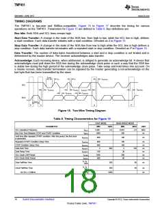
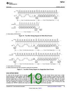
SCL
SDA
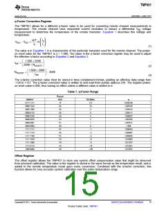
¼
1
0
0
1
1
0
0(1) R/W
P7 P6 P5 P4 P3
P2 P1
P0
¼
Start By
Master
ACK By
ACK By
Device
Device
Frame 2 Pointer Register Byte
Frame 1 Two-Wire Slave Address Byte
1
9
SCL
(Continued)
SDA
D7 D6 D5 D4 D3 D2 D1 D0
(Continued)
ACK By
Device
Stop By
Master
Frame 3 Data Byte 1
(1) Slave address 1001100 shown.
Figure 16. Two-Wire Timing Diagram for Write Word Format
1
9
1
9
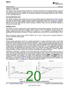
¼
SCL
SDA
1
0
0
1
1
0
0(1)
R/W
P7
P6
P5
P4
P3
P2
P1
P0
¼
Start By
Master
ACK By
ACK By
Device
Device
Frame 1 Two-Wire Slave Address Byte
Frame 2 Pointer Register Byte
1
9
1
9
SCL
¼
(Continued)
SDA
0(1)
¼
1
0
1
0
0
1
R/W
D7
D6
D5
D4 D3
D2
D1
D0
(Continued)
Start By
Master
ACK By
From
Device
NACK By
Master(2)
Device
Frame 3 Two-Wire Slave Address Byte
Frame 4 Data Byte 1 Read Register
(1) Slave address 1001100 shown.
(2) Master should leave SDA high to terminate a single-byte read operation.
Figure 17. Two-Wire Timing Diagram for Single-Byte Read Format
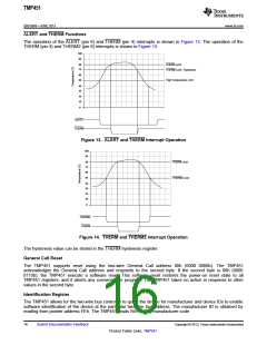
HIGH-SPEED MODE
In order for the two-wire bus to operate at frequencies above 400 kHz, the master device must issue a high-
speed mode (Hs-mode) master code (0000 1xxx) as the first byte after a start condition to switch the bus to high-
speed operation. The TMP451 does not acknowledge this byte, but switches the input filters on SDA and SCL
and the output filter on SDA to operate in HS-mode, allowing transfers at up to 2.5 MHz. After the Hs-mode
master code has been issued, the master transmits a two-wire slave address to initiate a data transfer operation.
The bus continues to operate in Hs-mode until a stop condition occurs on the bus. Upon receiving the stop
condition, the TMP451 switches the input and output filters back to fast mode operation.
Copyright © 2013, Texas Instruments Incorporated
Submit Documentation Feedback
19
Product Folder Links: TMP451

 TI [ TEXAS INSTRUMENTS ]